


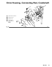

32 308-548
Drain
V
alve
WARNING
INJECTION
HAZARD
T
o reduce the risk of serious injury
,
whenever you are instructed to relieve
pressure, follow the
Pressure Relief
Procedure
on page 9.
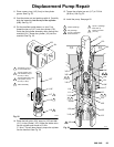
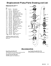
44
42a
42b
43
45
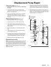
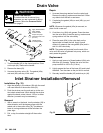
Apply
thread sealant
Handle shown
in closed position
Apply grease
to face of base
42
T
orque into pump
manifold to 185 in–lb
(21 N.m)
42c
42d
Fig.
32
02819
1
3
4
2
1
2
3
4
1. T
urn the handle (45) to the closed position. Drive
out the pin (44). Remove the handle.
2.
Remove the base (43).
3.
Unscrew the drain valve (42). The gasket (42a)
and seat (42b) will stay in the valve.
Repair
1.
Unscrew the spring retainer from the valve body
.
Remove the spring, washers and stem/ball. Clean
any debris from the ball or seat area.
2.
If replacing the gasket (42a) or seat (42b), pry out
the gasket.
NOTE:
Whenever the gasket (42a) is removed, re
-
place it with a new one.
3.
Coat the o-ring (42d) with grease. Press the stem
into the valve body
. Install the spring, washers and
spring retainer into the valve body
.
4.
Place the seat (42b) in the valve body so the
lapped side is toward the ball. Apply a small
amount of grease to the new gasket (42a) and in
-
stall it in the valve body
.
NOTE:
The gasket will protrude from the end of the
valve until the valve is tightened into pump, which cor
-
rectly seats the gasket.
Replacement
1.
Apply a small amount of thread sealant (42e) onto
the valve (42) threads. T
ighten the valve into the
pump manifold to 185 in–lb (21 N.m).
2.
Lightly grease the face of the base (43) and install
the base. T
urn the stem so the pin hole is vertical.
3.
Securely install the handle (45) and drive pin (44).
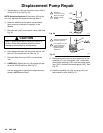
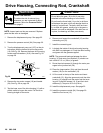
Inlet
Strainer Installation/Removal
Installation (Fig. 33)
1. Align
the keyway in the strainer (39) with the small
nub near the end of the suction tube (32).
2.
Push the strainer over the nub and up to the suc
-
tion tube’
s raised band. While holding the strainer
against the band, rotate it about 1/2 turn in either
direction (a wrench may be necessary).
Removal
1.
With a wrench or the hand, turn the strainer (39) in
either direction until the keyway aligns with the
raised nub in the suction tube (32). A sudden re
-
lease in turning resistance will be felt when the
parts align.
2.
Pull, or tap, the strainer straight of
f the suction
tube.
39
Fig. 33
04717
32