


308-548 27
Motor
Start Board
WARNING
INJECTION
HAZARD
T
o reduce the risk of serious injury
,
whenever you are instructed to relieve
pressure, follow the
Pressure Relief
Procedure
on page 9.
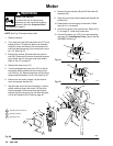
NOTE:
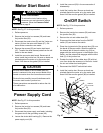
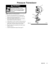
See Fig. 27 for this procedure.
1.
Relieve pressure.
2.
Remove the junction box screws (56) and lower
the junction box (59).
3.
Disconnect the motor wires (B) and the 3-wire con
-
nector (A) from the motor start board (47). Ob
-
serve where connections are made.
4.
Remove the screws (58) and motor start board
(47). T
ransfer the white thermal paste from the old
board to the new board.
5.
Install the new motor start board. Reconnect all
wires. Install the junction box. Be sure no leads are
pinched against the motor or by the motor start
board. Also be sure the gasket (89) is installed.
Be sure the flat blade of the insulated male con
-
nector is centered in the wrap–around blade of the
female connector when the connections are made.
Route all wires carefully to avoid interference with
the motor start board or junction box.
These precautions are essential to reduce the risk
of a malfunction.
CAUTION
Power
Supply Cord
NOTE:
See Fig. 27 for this procedure.
1.
Relieve pressure.
2.
Remove the junction box screws (56) and lower
the junction box (59).
3.
Disconnect the power supply cord leads, including
the green wire to the grounding screw (49).
4.
Loosen the strain relief bushing (51). Remove the
power supply cord (50).
5.
Install the new cord (50) in the reverse order of
disassembly.
6.
Install the junction box. Be sure no leads are
pinched against the motor or by the motor start
board. Also be sure the gasket (89) is installed.
On/Off
Switch
NOTE:
See Fig. 27 for this procedure.
1.
Relieve pressure.
2.
Remove the junction box screws (56) and lower
the junction box (59).
3.
Remove the nut and rubber boot (55).
4.
Disconnect the black wires from the ON/OFF
switch (52) and remove the switch.
5.
Place the ring terminal of the ground wire (53) over
the barrel of the new switch. Install the switch so
the internal tab of the anti-rotation ring (54) en
-
gages with the vertical groove in the threads of the
switch, and the external tab engages with the blind
hole (C) of the junction box.
6.
Powder the inside of the rubber boot (55) with tal
-
cum, then shake the excess out of the boot. Install
the nut and rubber boot and tighten.
7.
Reconnect the ON/OFF switch black wires.
8.
Install the junction box. Be sure no leads are
pinched against the motor or by the motor start
board. Also be sure the gasket (89) is installed.
52
04720
56
BLACK
47
54
55
53
50
51
49
GREEN
MOTOR
BLACK/
WHITE
59
58
RED
A
B
GREEN/
YELLOW
C
Fig. 27
89