


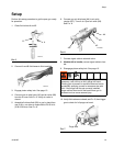
Setup
313872B 21
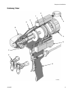
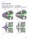
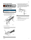
Optional Hose Position
As shipped, fluid inlet swivel fittings point to rear of the
gun. If desired, use the following procedure to make the
fluid inlet swivel fittings point downward.
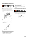
1. Follow Pressure Relief Procedure, page 22.
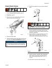
2. Disconnect air quick coupler (AC). Use hex nut
driver to remove fluid manifold (AD).
3. Disconnect signal cable.
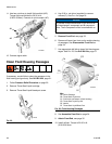
4. Place a cap over the end of each hose. Disconnect
fluid hoses from inlet swivels (AE). Remove plugs
from optional inlets (AG).
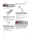
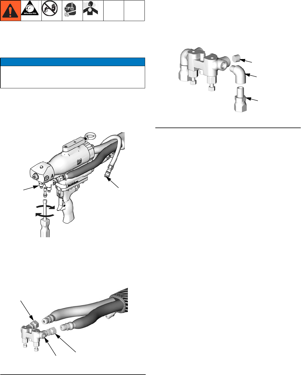
5. Apply thread sealant to plugs (AH), elbows (AJ),
and male threads of swivels (AE). Install
elbows (AJ) in optional inlets, facing down. See FIG.
11. Install swivels in elbows. Be sure to install the A
swivel in the A side. Install plugs (AH) where swivels
had been. Torque all parts to 235-245 in-lb
(26.6-27.7 N•m).
6. Connect the A hose to the A swivel and the B hose
to the B swivel.
7. Attach fluid manifold (AD) to gun. Torque fluid mani-
fold bolt to 20-30 in-lb (2.26-3.39 N•m).
8. Connect air quick coupler (AC).
NOTICE
To prevent cross-contamination of gun’s wetted parts,
do not interchange A component (isocyanate) and B
component (resin) parts.
FIG.10
TI14463a
AD
AC
TI2417a
AE
AE
AG
FIG.11
TI2646
AH
AJ
AE