


Repair
34 313872B
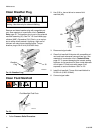
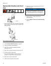
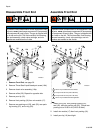
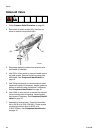
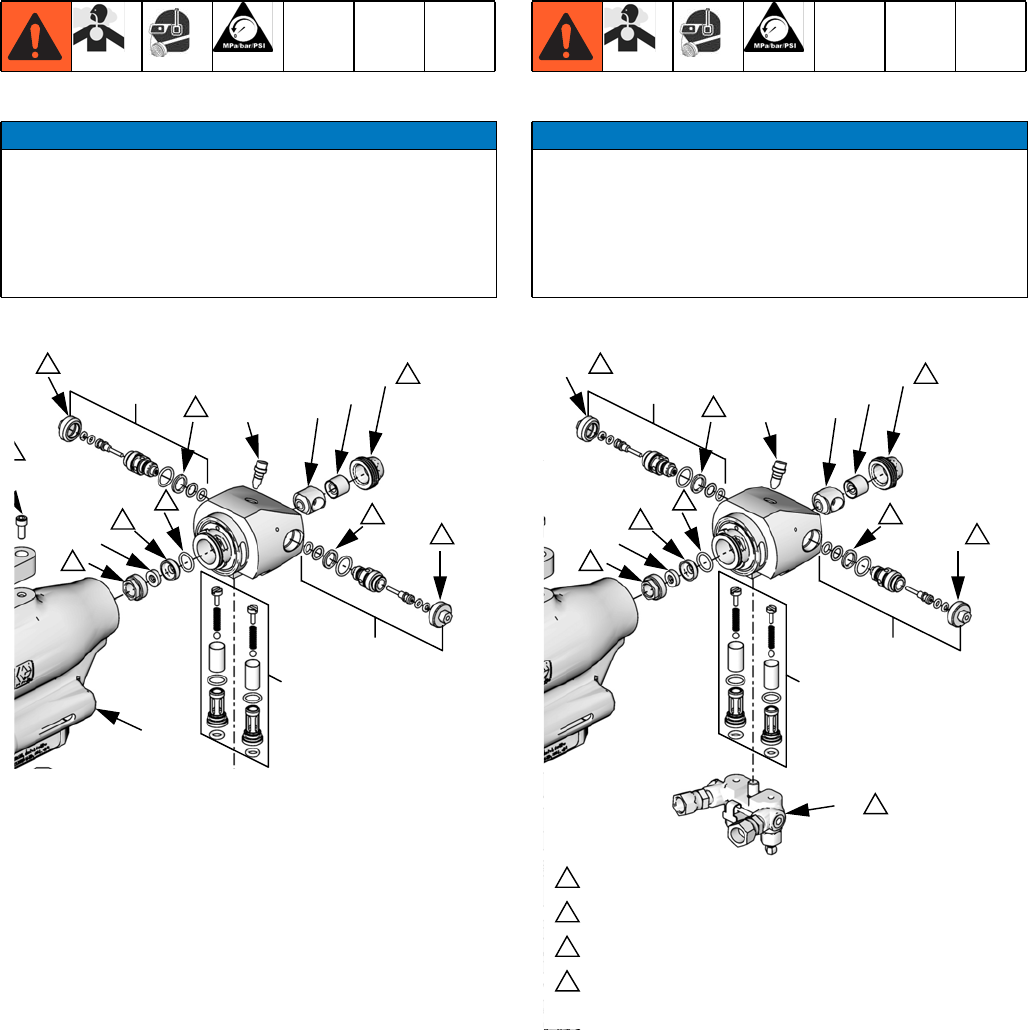
Disassemble Front End
1. Remove Front End, see page 33.
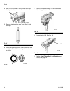
2. Remove Throat Seal Liquid bleed port screw (16b).
3. Remove check valve assembly (16a).
4. Remove orifice (25). Repeat for opposite side.
5. Remove pour tip (19).
6. Remove front packing (18) then mix module (17).
7. Remove rear packing nut (23), seal (22), rear pack-
ing housing (21), and o-ring (20).
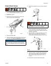
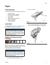
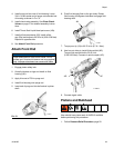
Assemble Front End
1. Install o-ring (20), rear packing housing (21),
seal (22), and rear packing nut (23). Torque rear
packing nut to 20-30 in-lb (2.26-3.39 N•m).
2. Install mix module (17) then front packing (18).
3. Install pour tip (19) hand-tight.
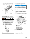
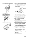
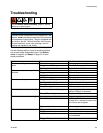
NOTICE
To prevent cross-contamination of the equipment’s wet-
ted parts, never interchange component A (isocyanate)
and component B (resin) parts. The gun is shipped with
the A side on the left. The fluid manifold, fluid housing,
side seal assembly, check valve cartridge, and mix
chamber are marked on the A side.
26
25
16b
17
18
19
16a
20
21
22
23
1
1
1
3
6
3
3
3
7
7
ti14469a1
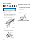
NOTICE
To prevent cross-contamination of the equipment’s wet-
ted parts, never interchange component A (isocyanate)
and component B (resin) parts. The gun is shipped with
the A side on the left. The fluid manifold, fluid housing,
side seal assembly, check valve cartridge, and mix
chamber are marked on the A side.
26
25
16b
17
18
19
28
16a
20
21
22
23
29
30
31
32
35
34
1
1
3
6
3
3
3
3
5
3
7
7
25a
26a
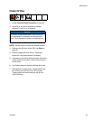
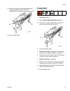
Part is only included with 375 orifices.
Torque to 20-30 in-lb (2.26-3.39 N•m)
Torque to 60-70 in-lb (6.78-7.91 N•m)
Part is only included with 250 applicator.
1
3
6
7
ti14469a1