


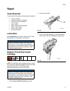

Maintenance
313872B 27
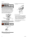
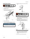
Clean Check Valves
1. Follow Pressure Relief Procedure, page 22.
2. Flush Gun, page 25.
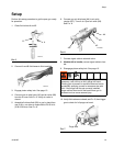
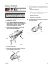
3. Disconnect air quick coupler (AC). Use hex nut
driver to remove fluid manifold (AD).
4. Disconnect signal cable.
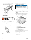
5. Clean and inspect check valve mating surfaces and
fluid ports. See Clean Fluid Manifold on page 26.
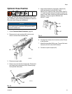
6. Use flat tip screwdriver to pry out check valves at
notch.
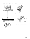
7. Press on ball (BC) to test check valve for proper
movement and spring action. Replace check valve
assembly if necessary.
8. Slide filter (BD) off. Clean and inspect parts. Thor-
oughly inspect o-rings (BE, BG). If necessary,
remove screw (BA) and disassemble check valve.
9. Liberally lubricate o-rings (BE, BG). Reassemble
check valves. Screw (BA) should be flush with
check valve housing surface (within 1/16 in. or
1.5 mm).
10. Install check valves into fluid housing (AK).
NOTICE
To prevent cross-contamination of the check valves,
do not interchange A component and B component
parts. The A component check valve is marked with
an A.
TI14463a
AD
AC
Damaged check valve o-rings may result in external
leakage. Replace o-rings if worn or damaged.
FIG.21
TI14464a
AK
B
A
BB
BC
BD
BE
BF
BG
TI14464a
BA