


Repair
313872B 35
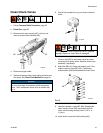
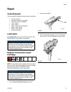
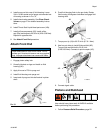
4. Install purge rod into rear of fluid housing. Leave
3/4 in. of ball socket end of purge rod extended out
of housing as shown in FIG.31.
5. Install check valve assembly. See Clean Check
Valves on page 27 for detailed assembly instruc-
tions.
6. Install Throat Seal Liquid bleed port screw (16b).
7. Install orifice components (25). Install orifice
cap (25a) and torque to 20-30 in-lb (2.26-3.39 N•m).
Repeat for opposite side.
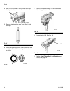
8. See Attach Front End procedure.
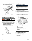
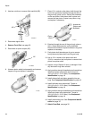
Attach Front End
1. Engage piston safety lock.
2. Liberally lubricate o-rings and install on fluid
housing (AK).
3. Apply thin coat of TSL to purge rod.
4. Install fluid housing onto purge rod.
5. Insert end of purge rod into ball socket in piston
shaft.
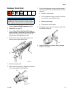
6. Push fluid housing flush to the gun body. Rotate
fluid housing 45 degrees clockwise to engage fluid
housing slots.
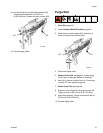
7. Torque pour tip (19) to 60-70 in-lb (6.7-9.1 N•m).
8. Use hex nut driver to install fluid manifold (AD).
Torque fluid manifold bolt to 20-30 in-lb
(2.26-3.39 N•m). Connect air quick coupler (AC).
9. Connect signal cable.
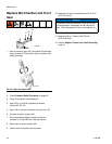
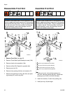
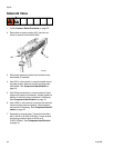
Pistons and Bulkhead
User should have piston seals kit 24D312 available
before performing this procedure.
1. Follow Pressure Relief Procedure, page 22.
NOTICE
Proper attachment of front end is critical. Do not
operate gun if front end is loose or not snug against
body. Improper attachment can cause slow leaks.
FIG.31
ti14482a
ti14483a
AK
TI14484a
AD
AC