


Maintenance
28 313872B
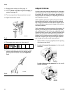
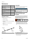
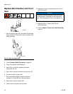
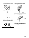
11. Use hex nut driver to install fluid manifold (AD).
Torque fluid manifold bolt to 20-30 in-lb
(2.26-3.39 N•m). Connect air quick coupler (AC).
12. Connect signal cable.
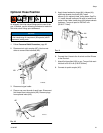
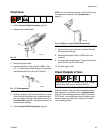
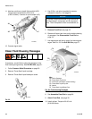
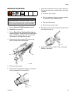
Clean Fluid Housing Passages
If necessary, use drill bits to clean the passages in the
fluid housing and gun body. See Drill Bit Kits, page 51.
1. Follow Pressure Relief Procedure on page 22.
2. Remove Throat Seal Liquid cartridge.
3. Remove Throat Seal Liquid bleed port screw.
4. Use 5/16 in. nut driver (supplied) to remove
orifices (C). See FIG. 4 on page 16.
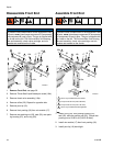
5. Remove Front End, see page 33.
6. Remove all items from front end to enable cleaning
of passages. See Disassemble Front End on
page 34.
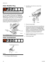
7. Use appropriate drill bits to clean fluid housing pas-
sages. See FIG. 23. See Drill Bit Kits, page 51.
8. See Assemble Front End on page 34.
9. Attach Front End, see page 35.
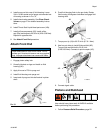
10. Install orifices. Torque to 20-30 in-lb
(2.26-3.39 N•m).
FIG.22
TI14484a
AD
AC
AK
ti14478a
NOTICE
To prevent cross-contamination of the orifices do
not interchange A component and B component
parts. The A component orifice is marked with an
A.
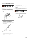
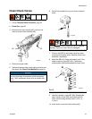
FIG. 23: Fluid Housing Passages
TI14480a
Key:
CA Orifice Passage
CB Throat Seal Liquid Inlet
CC Fluid Inlets (on bottom of fluid housing)
CD Throat Seal Liquid Pop-Off
CE Nozzle
CF Throat Seal Liquid Bleed Port
CA
CB
CA
CD
CC
CE
CF
CC