


10 308741
Setup
6. Adjust the Spray Pattern (continued)
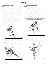
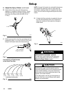
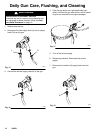
B. Adjust the fluid flow using the fluid pressure
regulator (L) installed in the gun fluid line. Typical
industrial flow rates will vary with regulator pres-
sures from 5 to 30 psi (34 to 210 kPa, 0.3 to
2.1 bar).
Fig. 8
L
7019A
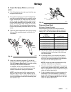
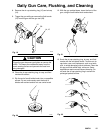
C. Hold the gun parallel to the floor and adjust the fluid
pressure to yield a 1 to 6 inch (25.4 to 152.4 mm)
straight fluid stream before the stream falls off.
Fig. 9
1–6 in.
(25.4–152.4 mm)
straight fluid stream
7037
A
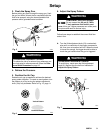
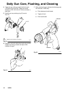
Fluid Velocity of Fluid Nozzles
at the Same Flow Rate
Fig. 10
0.042
(1.067)
0.055
(1.397)
0.070
(1.778)
0.086
(2.184)
0.110
(2.794)
Orifice Size in inches (mm)
7038A
NOTE: A larger fluid nozzle at a reduced fluid pressure
will maintain the same flow rate, but slow down the
fluid stream (velocity). When air is applied, this allows
the air to act on the fluid longer and improve the atom-
ization.
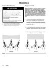
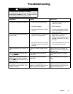
D. If further fluid flow restriction is needed at the gun,
turn the fluid adjustment knob (21) clockwise to
reduce the volume of fluid output by limiting the
needle travel.
Fig. 11
21
close
7039
A
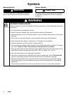
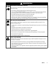
WARNING
PRESSURIZED EQUIPMENT HAZARD
To avoid injury, never open the fluid adjustment
knob (21) beyond the one half turn indicated in
Adjust the Spray Pattern, page 9.
CAUTION
Restricting the trigger and fluid needle travel by
continuously spraying with the fluid adjustment knob
closed (turned clockwise), will cause accelerated
abrasive wear on the fluid needle and wear on the
trigger/air valve shaft interface.
For the best results, use the gun fluid regulator to
adjust the fluid flow or use a different size needle/
nozzle/air cap combination.