


308741 19
Service
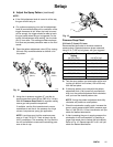
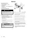
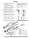
12. Place the new fluid packings (5) and packing
screw (8) onto the needle (13). See Fig. 27 for the
orientation of the parts.
13. Insert the fluid needle (13) into the back of the
insert (4) to install the fluid packings (5).
14. Tighten the packing screw (8) just enough to hold
the packings (5) in the insert (4). The needle (13)
must move freely. Remove the needle.
NOTE: To ensure proper alignment of the parts, follow
the next steps in the order they are given.
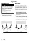
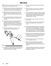
15. Slide the insert (4) into the spray housing (2a). See
Fig. 28. Align the housing with the slot and lip (A)
on the gun and slide the insert into the gun
body (1).
16. Tighten the hex nut (9) onto the insert (4) hand-
tight, then loosen the nut about one turn so the
insert (4) and spray housing sit loosely in the gun
body.
17. Lubricate and install the fluid needle (13).
18. Lubricate the fluid adjustment knob threads (21),
and install the fluid spring (23) and adjustment
knob.
19. Install the trigger (10), pin (17), and screw (11).
Torque the screw to 20–30 in-lb (2.3–3.4 NSm).
20. To avoid galling of the fluid nozzle seat in the insert
(4), apply a thin film of lubricant to the seat. Trigger
the gun while you install the fluid nozzle (12) with
the gun tool (28). Torque the nozzle securely to
145–155 in-lb (16–17 NSm).
21. Tighten the hex nut (9) securely to 125–135 in-lb
(14–15 NSm).
Fig. 27
02024
13
5
1
Spreader; tapered end down
U-cup; lips face up
Spacer
2
3
1
2
3
8
4
1
4
2a
*2b
*5
8
9
10
11
17
12
13
14
13a
15
22
20*
23
19
24
25c
21
25a
*25b
25d
7584A
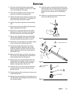
Fi
g
. 28
1
Lightly lubricate
Lightly lubricate threads
Torque to 125–135 in-lb (14–15 NSm)
Torque to 20–30 in-lb (2.3–3.4 NSm)
U-cup lips face air valve assembly (26)
U-cup lips face away from nut (19/25a)
Torque to 145–155 in-lb (16–17 NSm)
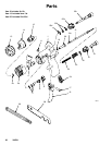
*Parts included in Repair Kit 239–639
2
3
4
A
5
6
1
3
3
3
3
2
1
6
4
2
6
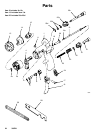
Item 2 includes 2a–2b
Item 13 includes item 13a
Item 25 includes 25a–25d
26*
16*
1
5
7
7
1