


308741 21
Service
11. Place the new fluid packings (5) and packing
screw (8) onto the needle (13). See Fig. 27, page
19, for the orientation of the parts.
12. Insert the fluid needle (13) into the back of the
insert (4) to install the fluid packings (5).
13. Tighten the packing screw (8) just enough to hold
the packings (5) in the insert (4). The needle (13)
must move freely. Remove the needle.
14. Unscrew the pattern adjustment valve assembly
(25).
15. Remove the retaining ring (25d) and unscrew the
pattern adjustment valve (25c).
16. Remove the u-cup seals (25b) from the pattern
adjustment nut (25a). Be careful not to damage
the seal surface or the nut’s internal threads.
17. One at a time, install the new u-cup seals (25b)
with the seal installation tool (29); the u-cup lips
must face toward the tool as shown in Fig. 31.
18. Push each u-cup seal (25b) into the pattern adjust-
ment nut (25a) until a definite snap is felt.
19. Lubricate the pattern adjustment valve (25c)
threads and install the valve into the nut (25a).
Install the retaining ring (25d), then back out the
pattern adjustment valve as far as the retaining
ring allows it to go.
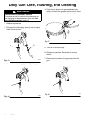
20. Remove the fluid valve nut (19), air valve spring
(22), and air valve assembly (26). Discard the air
valve assembly. See Fig. 28, page 19.
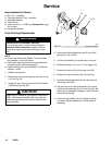
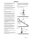
21. Remove the u-cup (16) from the gun body. The
threaded end of the needle (13) can be used to
push out the u-cup. Be careful not to damage
needle or sealing surface. See Fig. 29.
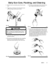
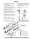
22. Place the new u-cup (16) on the seal installation
tool (29), with the u-cup lips facing the tool as
shown in Fig. 30.
23. Push the packing (16) into the back of the gun until
a definite snap is felt.
24. Remove the u-cup seal (20) from the fluid valve nut
(19). Be careful not to damage the seal surface or the
nut’s internal threads.
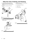
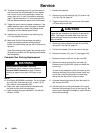
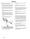
25. Install the new u-cup seal (20) with the seal instal-
lation tool (29); the u-cup lips must face toward the
tool as shown in Fig. 31. This will help apply even
pressure to the u-cup lips and avoid damaging
them.
26. Push the u-cup seal (20) into the fluid valve nut
(19) until a definite snap is felt.
Fig. 29
13
Fig. 30
1
U-cup lips face the tool
16
29
1
Fig. 31
20 or 25b
29
1
1
U-cup lips face
the tool
19 or 25a