


308936 13
Gun Setup
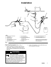
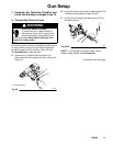
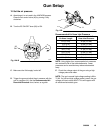
5. Connect the fluid hose.
A. Before connecting the fluid line, blow it out with air
and flush it with solvent. Use solvent which is com-
patible with the fluid to be sprayed.
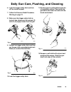
B. Connect the static-free fluid hose (F) to the 1/4–18
npsm gun fluid fitting (10).
Fig. 5B
01993A
F
10
NOTE: The PRO AA4500 spray gun has a 100 mesh
in-line fluid inlet filter. A 60 mesh filter is also available.
See Accessories.
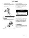
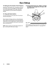
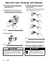
C. Connect the other end of the fluid hose (F) to a
grounded, filtered, and regulated fluid line (G).
G
Fig. 5C
01994A
F
6. Flush the spray gun.
Before running any paint through the spray gun, make
sure the trigger safety latch is in the locked position,
and the ES ON-OFF lever is turned to OFF, then
remove the spray tip. Flush the gun out with a solvent
that is compatible with the fluid to be sprayed, using
the lowest possible pressure.
7. Follow the Pressure Relief Procedure.
WARNING
INJECTION HAZARD
To reduce the risk of a fluid injection
injury, always follow the Pressure Relief
Procedure on page 10 before removing
or installing the spray tip, pre-orifice air cap or tip
guard.
8. Select a spray tip.
The fluid output and pattern width depend on the size
of the spray tip, the fluid viscosity, and the fluid pres-
sure. Use the Spray Tip Selection Chart on page 47,
as a guide for selecting an appropriate spray tip for
your application or consult your authorized Graco
distributor. The orifice size of the spray tip is typically
one or two sizes larger than the pre-orifice size
selected below.
9. Select a pre-orifice
The fluid flow rate in UNICARB systems is controlled
by the pre-orifice size, in conjuction with the fluid
pressure. Use the pre-orifice selection chart on page
47 as a guide for selection.