


34 308936
Service
Fluid Needle Assembly Removal
1. Prepare the gun for service as instructed on page
28.
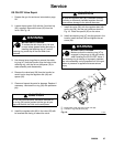
2. Remove the retaining nut (8), tip guard, (2), air cap
(1) and spray tip (9). See Fig. 7, page 29. You may
have to turn the air cap with the tip guard to
remove the air cap from the gun.
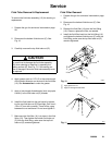
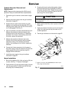
3. Trigger the gun and remove the seat housing (21)
with the 9 mm driver (64). See Fig. 8, page 29.
4. Remove the barrel as instructed on page 32.
5. Remove the trigger screws (4) and trigger (13).
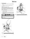
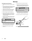
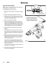
6. Place the 2 mm driver (58) in the back of the fluid
needle assembly (28). See Fig. 14. Push the tool
in and turn it counterclockwise about 12 full turns
to unthread the needle.
7. Insert the 2 mm driver (58) into the front of the gun
and push the fluid needle assembly (28) out the
back of the gun body.
CAUTION
To avoid damaging the needle assembly, be sure the
needle is completely unthreaded before pushing it
out of the barrel.
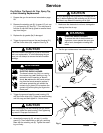
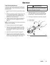
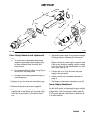
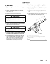
8. Install the fluid needle assembly (28) into the gun
barrel. See Fig. 15. Push in on the needle with the
2 mm driver (58) and tighten the assembly clock-
wise until just snug, then 1/4 to 1/2 turn tighter.
9. Install the trigger (13) and tighten the trigger
screws (4).
10. Assemble the barrel as instructed on page 36.
11. Trigger the gun and install the seat housing (21)
with the 9 mm driver (64). Tighten the seat housing
until it’s snug and then tighten it 1/8 turn more.
CAUTION
To avoid damaging the seat housing and gun barrel,
never over-tighten the seat housing. Over-tightening
may result in improper fluid shut-off.
12. Assemble the spray tip, air cap, and tip guard.
Then install them on the gun, securing them with
the retaining nut. Tighten the retaining nut firmly.
13. Test the gun resistance as instructed on page 25.
Fig. 15
28
13
4
02016