


308936 35
Service
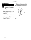
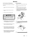
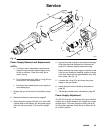
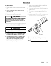
Fig. 16
7
35
37a
37b
18a
18
37
F
3
18b
18c
18d
18e
01953A
Power Supply Removal and Replacement
NOTES:
a. To avoid a loss in electrostatic performance,
inspect the gun handle’s power supply cavity
for dirt or moisture. Clean the cavity with a
clean, dry rag.
b. Do not expose the seal (18e) or o-ring (37a) to
solvents as it will damage them.
c. Be careful when handling the power supply to
avoid damaging it.
1. Prepare the gun for service as instructed on page
28.
2. Remove the barrel as instructed on page 32.
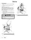
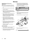
3. Grasp the power supply (18) with your hand. With
a gentle side to side motion, pull the power supply
free from the gun handle (7), then pull it straight
out.
4. Inspect the power supply for any physical damage.
Check the electrical resistance as instructed on
page 26. If needed, replace the power supply.
Before installing the power supply, inspect the seal
(18e) for any damage or swelling; replace if neces-
sary. Also, make sure the gaskets/pads (18a–18d)
are in place. See Fig. 16.
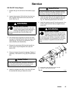
5. Lubricate the o-ring (37a) and insert the power
supply in the gun handle.
6. Install the barrel on the handle as instructed on
page 36.
7. Test the gun resistance as instructed on page 25.
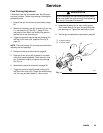
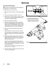
Power Supply Adjustment
The KV HI/LO switch, on the back of the gun manifold,
enables you to switch between full voltage and a lower
voltage output. The lower voltage is factory set at 60
kV, but can be adjusted. Place the pin in either the 45
kV or 60 kV position.