


G0492 12" X 36" Combo Lathe/Mill
-27-
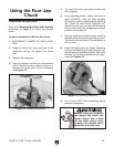
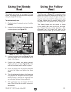
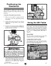
You can manually move the cutting tool around
the lathe/mill with the three handwheels shown
in Figure 30
.
S
Longitudinal Handwheel
The longitudinal handwheel moves the carriage
left or right along the bed. This control is help
-
ful when setting up the machine for turning or
when manual movement is desired during turning
operations.
Cross Slide Handwheel
The cross slide handwheel moves the top slide
toward and away from the work. Turning the dial
clockwise moves the slide toward the workpiece.
Compound Rest Handwheel
The compound rest handwheel controls the
position of the cutting tool relative to the
workpiece. The graduated dial is adjustable
using the same method as the dial on the
cross slide. Angle adjustment is held by two
hex nuts on the base of the compound rest.
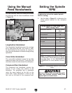
Figure 30. Carriage controls.
Cross Slide
Handwheel
Longitudinal
Handwheel
Compound
Rest
Handwheel
To determine and set the needed spindle
RPM for cutting:
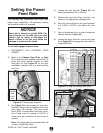
1. Use the table in Figure 31 to determine the
cutting speed required for the workpiece
material.
Cutting Speeds for High Speed Steel
(HSS) Cutting Tools
Workpiece Material Cutting Speed
(sfm)
Aluminum & alloys 300
Brass & Bronze 150
Copper 100
Cast Iron, soft 80
Cast Iron, hard 50
Mild Steel 90
Cast Steel 80
Alloy Steel, hard 40
Tool Steel 50
Stainless Steel 60
Titanium 50
Plastics 300-800
Wood 300-500
Figure 31. Cutting speed table for HSS cutting
tools.
Failure to follow RPM and feed rate guide-
lines may threaten operator safety from
ejected parts or broken tools.
Using the Manual
Feed Handwheels
Setting the Spindle
RPM
Note: For carbide cutting tools, double the
cutting speed. These values are a guide-
line only. Refer to the MACHINERY'S
HANDBOOK for more detailed informa-
tion.