


-30-
G0492 12" X 36" Combo Lathe/Mill
Your lathe is capable of cutting inch and metric
threads.
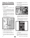
To setup for threading:
1. DISCONNECT THE LATHE/MILL FROM
POWER!
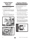
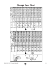
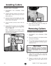
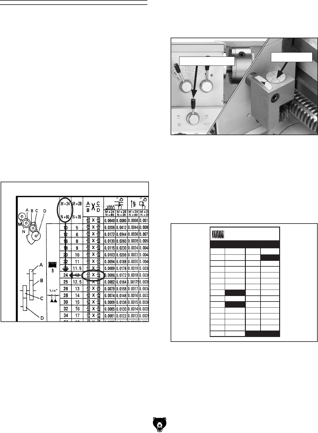
2. Refer to the Change Gear Chart on Page 31
or the chart on the inside of the change gear
door to determine the needed combination
of gears and which spindle location to install
each gear on.
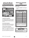
See
Figure 36 for examples of how gear com-
binations can achieve your needed threading
rate. For example: The chart shows that 24
TPI is needed.
Note: All change gears are stamped with the
number of teeth they have.
Figure 36. Using the change gear chart.
Longitudinal
Feed
Cross
Feed
Inch
Threading
Setup for Threading
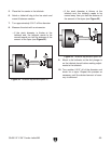
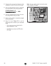
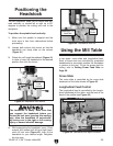
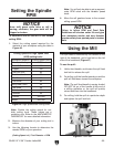
6. Use the leadscrew lever to select leadscrew
direction (
Figure 37).
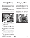
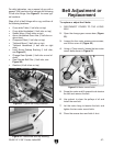
7. Setup the cutting tool, compound rest, and
cross slide to cut your threads; and loosen the
apron lock
(Figure 35).
3. Loosen the lash adjuster (Figure 33) and
swing the assembly out of the way.
4. Remove the required E-clips, lubricate, and
swap out the appropriate change gears.
5. Move the lash adjuster so the gear backlash
is at 0.003" to 0.008", and tighten the lock
nut.
Figure 37. Threading controls.
Thread Dial
Leadscrew Lever
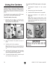
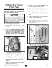
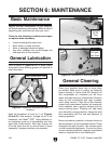
Figure 38. Thread dial table.
5
6
7
8
9
10
11
12
13
14
15
16
17
1-6
1 or 2
1 or
2
1 or
2
1 or 2
1 or 2
1 or
2
1 or
2
1 or 2
1 or
2
1 or
2
1 or
2
1 or
2
1 or
2
1
1
1
1
1
1
1
1-6
1-6
1-6
1-6
1-6
18
20
22
23
24
25
26
28
30
32
34
36
40
48
THREAD DIAL TABLE
LEAD SCREW PITCH 5 T.P.I.
12.5
11.5
T.P.I. DIAL T.P.I. DIAL
— If cutting inch threads, refer to the Thread
Dial Table in Figure
38 to use the thread
dial.
— If cutting metric threads, do not use the
thread dial. Instead, you must leave the
half nut engaged until the threading opera
-
tion is totally complete.
8. Loosen the apron lock bolt and use the feed
lever (
Figure 35).
9. While threading, keep your hand on the
half-nut lever, ready to disengage the apron
to avoid any potential for an apron/chuck
crash.