G0500/G1018/G1018HW 8" Jointers -39-
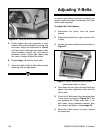
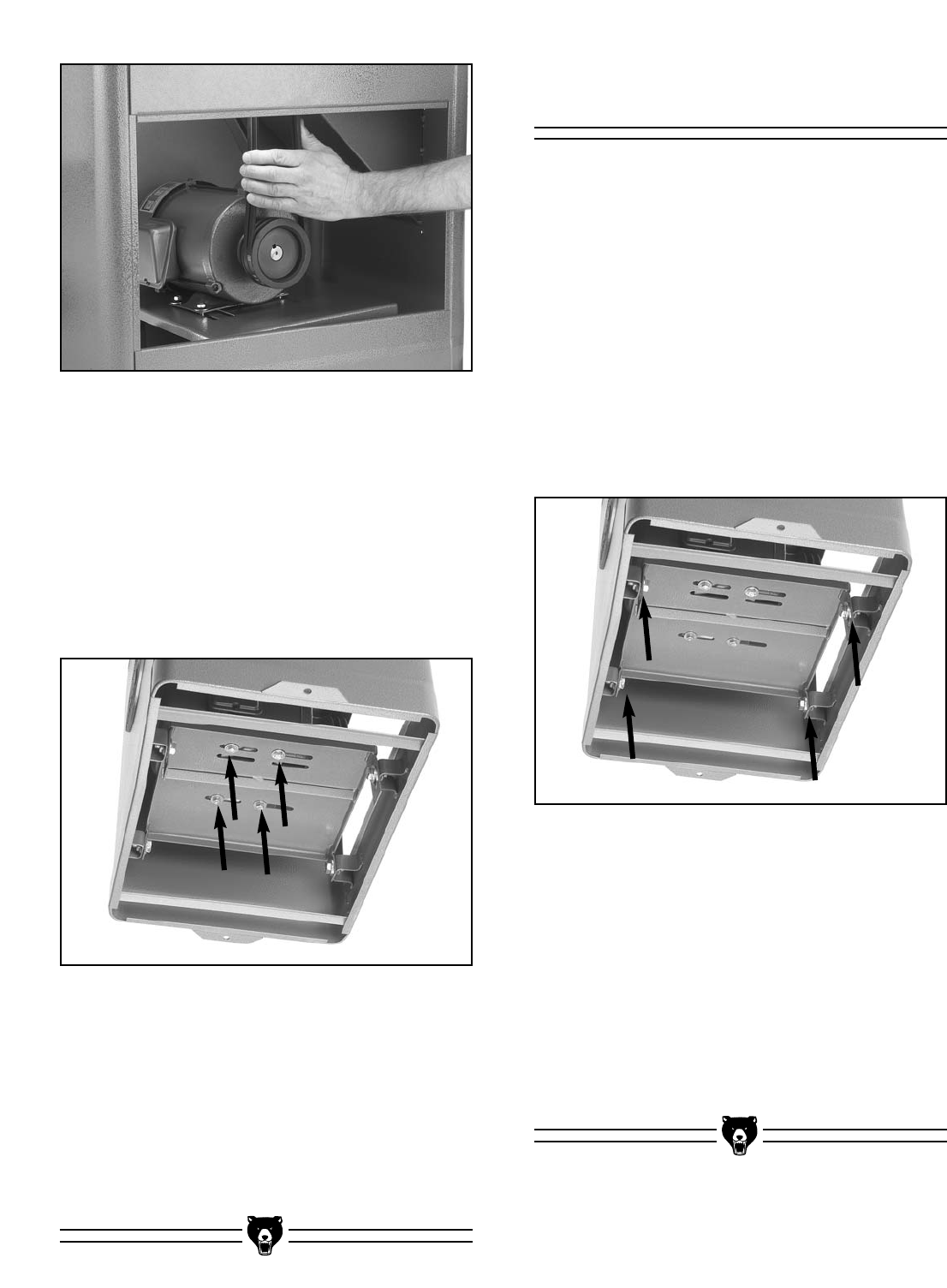
Figure 58. Checking V-belt tension.
Figure 59. Motor mount bolts(shown underneath
stand for clarity).
To adjust the V-belt alignment:
1. Disconnect the jointer from the power
source!
2. Remove the stand door to gain access to the
V-belts.
3. Loosen the motor mount bolts shown in
Figure 59.
4. Use a straightedge to align the motor and
cutterhead pulleys.
5. Tighten the motor mount bolts. Note—Minor
alignment changes can be made by loosen-
ing the setscrew on the pulleys and adjusting
them on their shaft. Replace the stand door.
Replacing V-Belt
During the life of your jointer, you will need to
replace the V-belts when they become cracked or
damaged.
To replace the V-belts:
1. Disconnect the jointer from the power
source!
2. Remove the stand door to gain access to the
V-belts.
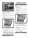
3. Loosen the motor adjustment bolts shown in
Figure 60.
4. Move the motor up to loosen and remove the
V-belts from the motor and cutterhead pul-
leys.
5. Install the new V-belts on the motor and cut-
terhead pulleys.
6. Adjust the V-belts to their proper tension.
7. Replace the stand door.
Figure 60. Motor adjustment bolts (shown
underneath stand for clarity).


