G0604 6" X 56" Jointer
-13-
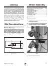
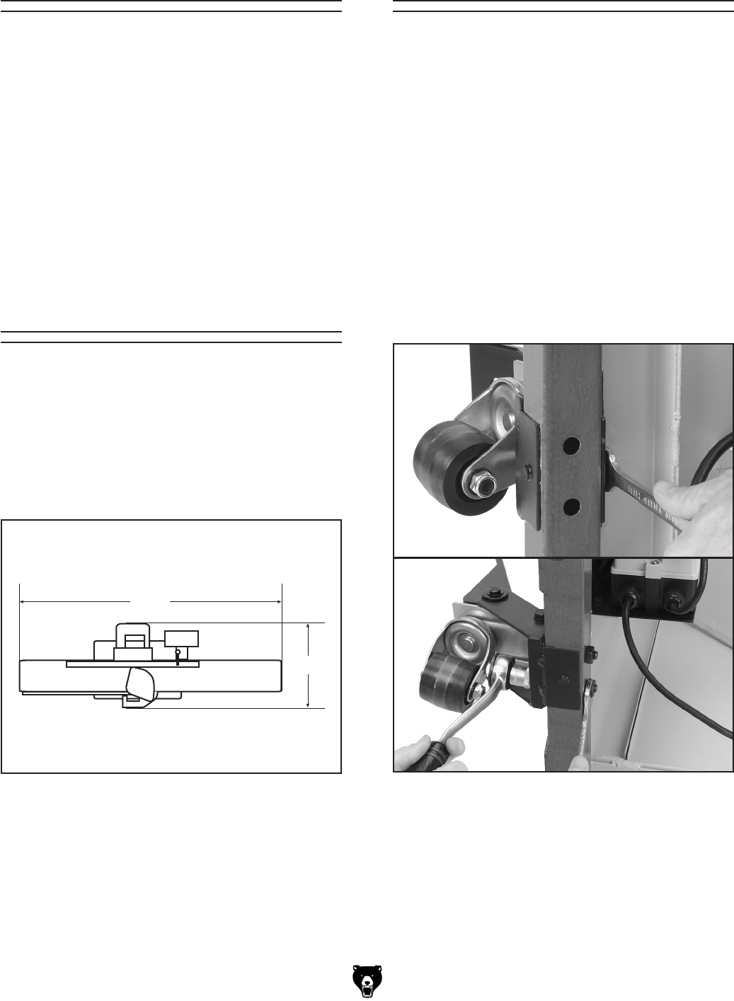
Figure 4. Model G0604 overhead view
dimensions.
Machine Placement
Consider the jointer dimensions and size of mate-
rial to be processed through each machine, and
space for auxiliary stands, work tables or other
machinery when establishing a location for your
jointer. See Figure
4 for the Model G0604 over-
head view dimensions.
The unpainted cast iron surfaces are coated with
a waxy oil to protect them from corrosion during
shipment. Remove this protective coating with a
solvent cleaner or citrus-based degreaser such
as Grizzly’s G7895 Degreaser. To clean thor
-
oughly, some parts may need to be removed. For
optimum performance from your machine,
make sure you clean all moving parts or slid
-
ing contact surfaces that are coated. Avoid
chlorine-based solvents, such as acetone or
brake parts cleaner, as they may damage painted
surfaces should they come in contact.
Site Considerations
Cleanup
55
1
⁄2"
25"
Components and Hardware Needed: Qty
Wheel Assembly ................................................
1
Stand Assembly w/Motor ...................................
1
Hex Bolt M8-1.25 x 50 .......................................
1
Flat Washer 8mm ..............................................
1
Hex Bolts M10-1.5 x 55 .....................................
2
Flat Washers 10mm ..........................................
2
Hex Nuts M10-1.5 .............................................
2
To attach
the wheel:
1. Carefully lay the stand on its side so you can
access the underside.
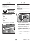
2. Bolt the wheel assembly to the stand with the
provided hardware as shown in Figure
5.
Wheel Assembly
Figure 5. Bolting the wheel assembly to the
stand.
3. Turn the stand rightside up.


