


-18-
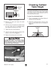
G0604 6" X 56" Jointer
Cutterhead Guard
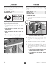
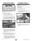
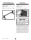
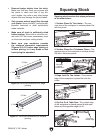
Figure 17. Installing the cutterhead guard.
3. Pull the cutterhead guard backward to ten-
sion the spring, then—while holding tension
on the guard—move the fence into regular
operating position and release the guard
against the fence.
4. Test the guard. When pulled back and
released, the guard should spring back over
the cutterhead and stop against the fence.
—If the guard does not spring back over the
cutterhead or drags across the table, rein-
stall it, making sure there is tension on the
shaft when it is installed, so it will spring
back over the fence.
Components and Hardware Needed: Qty
Cutterhead Guard ..............................................
1
To install the cutterhead guard:
1. Move the fence all the way back, then raise it
2" off the table and lock it in place.
2. Insert cutterhead guard shaft so the flat is fac-
ing the set screw, then tighten the set screw
against the shaft (see
Figure 17), keeping
the guard approximately
1
⁄8" off the table.
Components and Hardware Needed: Qty
Pedestal Switch .................................................
1
Cap Screws M8-1.25 x 20 .................................
2
Lock Washers 8mm ...........................................
2
Flat Washers 8mm ............................................
2
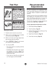
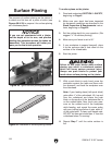
To install the pedestal switch:
1. Attach the pedestal switch with the cap
screws, lock washers, and flat washers, as
shown in
Figure 18.
Pedestal Switch
The cutterhead guard is a critical safety fea-
ture on this machine—you MUST install and
verify its operation before using the joint
-
er! Failure to install this guard will greatly
increase the chances of a serious injury.
Figure 18. Attaching pedestal switch to stand.
2. Thread the excess motor cord through the
access hole in the stand, and plug it into the
switch cord.