


-12-
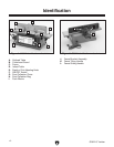
G0612 6" Jointer
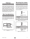
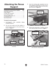
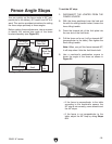
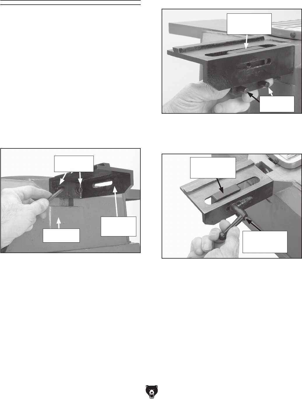
3. Insert the locking plate assembly into the
fence support, positioning it so the two pins
are against the bottom edge of the fence sup
-
port as shown in
Figure 10.
4. Secure the locking plate in position with the
fence sliding handle as shown in
Figure 11.
Figure 10. Inserting the locking plate.
Figure 11. Securing the locking plate assembly
with the fence sliding handle.
Attaching the Fence
Support
Components and Hardware Needed: Qty
Jointer Bed Assembly ........................................
1
Fence Support ...................................................
1
Locking Plate Assembly ....................................
1
Fence Sliding Handle .......................................
1
Cap Screws M8-1.25 x 20 .................................
2
Lock Washers 8mm ...........................................
2
Hex Wrench 6mm ..............................................
1
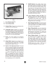
To attach the fence support:
1. DISCONNECT THE JOINTER FROM
POWER SOURCE!
2. Use two cap screws and lock washers to
attach the fence support to the jointer bed as
shown in Figure
9.
Figure 9. Attaching the fence support to the bed
assembly.
Locking
Plate Pins
Fence
Support
Locking Plate
Assembly
Locking Plate
Assembly
Fence Sliding
Handle
Jointer Bed
Cap Screws