


-18-
G0612 6" Jointer
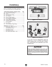
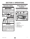
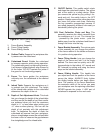
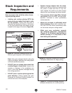
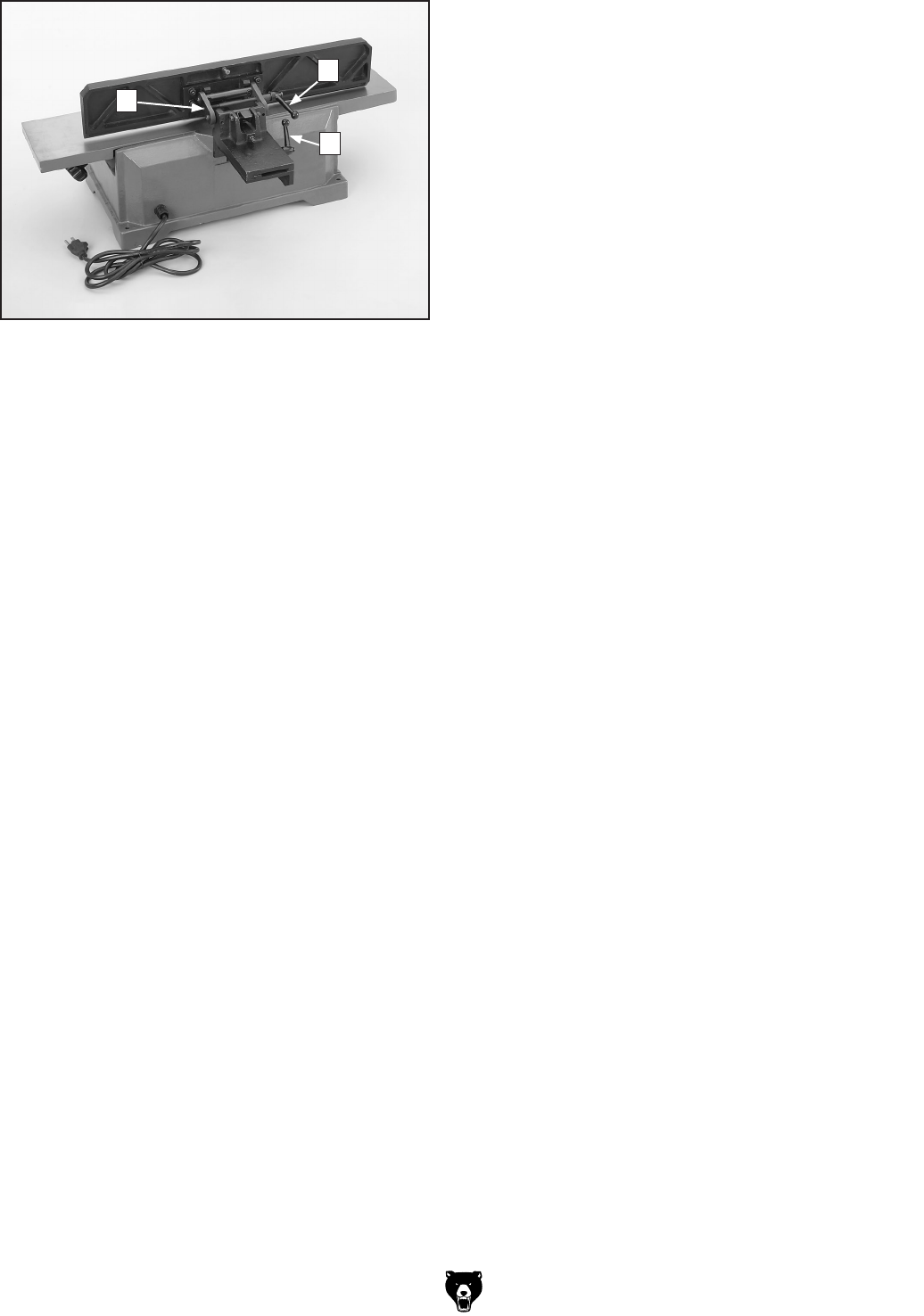
Figure 22. G0612 parts and controls (back
view).
I. Fence Bracket Assembly
J. Fence Tilting Handle
K. Fence Sliding Handle
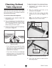
A. Outfeed Table: Supports the workpiece after
it passes over the cutterhead.
B. Cutterhead Guard
: Shields the cutterhead
to increase operator safety during operation.
The cutterhead guard is under spring tension;
it will always (unless blocked) snap forward to
hit the fence. DO NOT operate the jointer if
the guard is not functioning properly.
C. Fence
: The fence guides the workpiece
uniformly over the cutterhead at the desired
angle.
D. Infeed Table
: Supports the workpiece as it
is pushed over the cutterhead. The height
of the infeed table relative to the cutterhead
determines the depth of the cut.
E. Depth of Cut Adjustment Knob
: This knob
lets you change the height of the infeed table
and thus control the depth of cut. Best results
are achieved when you limit the maximum
depth to
1
/8" or less when edge jointing and
1
/32" when surface planing. You can set the
depth of cut precisely with this adjustment
knob. To determine the depth of stock the
cutterhead will remove from your workpiece,
place a straightedge across the outfeed table
and use a ruler to measure the gap between
the straightedge and the infeed table.
F. ON/OFF Switch
: This paddle switch starts
and stops the cutterhead rotation. The yellow
part of the switch is a safety device. When
you remove this yellow key (by pulling it for
-
ward and out), the switch locks in the
OFF
position. Always remove this yellow key when
you leave the jointer work area. Removing
the key prevents unsupervised persons in
your shop (especially children) from easily or
accidentally starting the jointer.
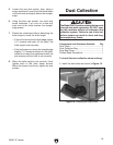
G/H. Dust Collection Chute and Bag: This
assembly receives the debris removed from
the workpiece as it is cut. The internal fan
- powered by the jointer motor - pulls the
debris away from the cutterhead and blows it
through the chute into the bag.
I. Fence Bracket Assembly
: The various parts
of this assembly
let you change the position
of the fence relative to the tables and secure
it in position during operation.
J. Fence Tilting Handle
: Lets you change the
angle of the fence and lock it at the angle
desired. The fence can be quickly set to 90
°
(perpendicular to the
tables), 45° inward and
45° outward by setting and using the fence
stops on the bracket assembly.
K. Fence Sliding Handle
: This handle lets
you adjust and lock the position of the fence
across the tables.
ALWAYS firmly tighten
the sliding handle before you begin opera
-
tions. The position of the fence determines
the maximum width of the cut as you pass
your workpiece over the spinning cutterhead.
NEVER operate the jointer if ANY part of
cutterhead is exposed on the work area.
I
J
K