


G0612 6" Jointer
-13-
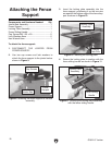
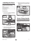
Installing the Fence
Components and Hardware Needed: Qty
Jointer Bed Assembly with Fence Support .......
1
Fence ................................................................. 1
Fence Bracket Assembly ...................................
1
Fence Tilting Handle .........................................
1
Cap Screws M8-1.25 x 20 .................................
4
Lock Washers 8mm ...........................................
4
Hex Wrench 6mm ..............................................
1
To install the fence:
1. Use the four cap screws and washers to
attach the fence to the fence bracket assem
-
bly, as shown in Figure
12.
2. Slide the fence bracket assembly over and
onto the dovetails of the support and locking
plate as shown in Figure
13.
Figure 12. Attaching the fence to the fence
bracket assembly.
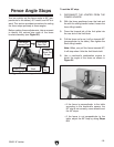
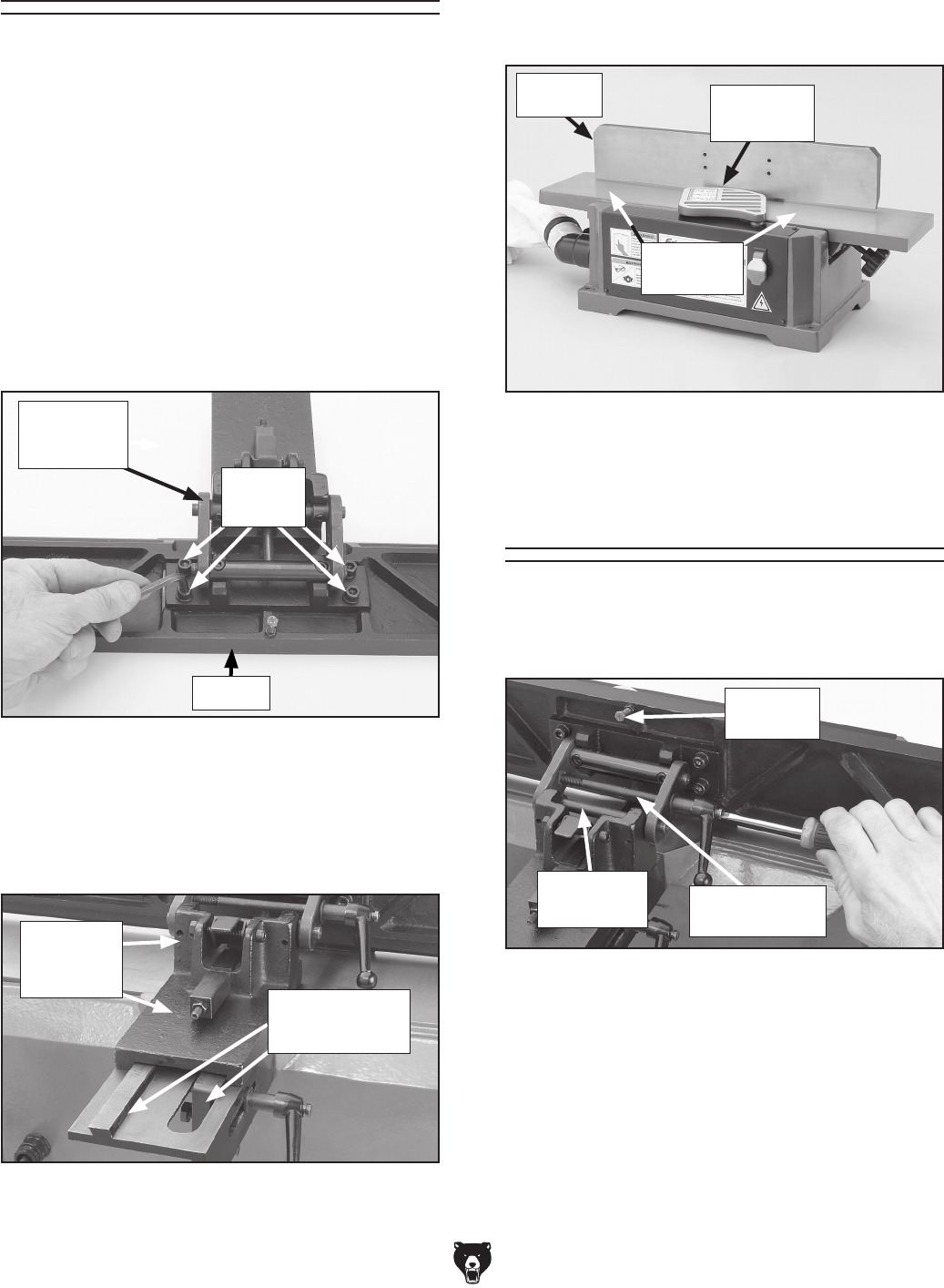
3. Slide the fence forward until it contacts the
cutterhead guard and the cutterhead guard
completely covers the cutterhead as shown
in Figure 14.
Bracket
Assembly
Fence
Figure 14. Fence postitioned over the jointer
tables.
Fence
Cutterhead
Guard
Jointer
Tables
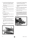
Fence Tilting Handle
Install the fence tilting handle by screwing the
handle shaft into the bracket assembly as shown
in Figure
15.
Figure 15. Installing the fence tilting handle.
Bracket
Assembly
Fence Tilting
Handle Shaft
Outward
Stop
Cap
Screws
Figure 13. Sliding the fence bracket onto the
fence support dovetails.
Fence Support
Dovetails
Fence
Bracket
Assembly