


-14-
G0622 4" X 6" Metal Cutting Bandsaw
Stand Assembly
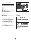
Components and Hardware Needed: Qty
Bandsaw .............................................................1
Hex Bolts M6-1 x 12 ...........................................
8
Flat Washer 6
mm .............................................12
Hex Nuts M6-1 .................................................
12
Stand Legs .........................................................
2
Corner Support Braces ......................................
4
Axle ....................................................................
1
Wheels ................................................................
2
Cotter Pins ..........................................................
4
Transport Handle ................................................
1
Wheel Mounting Bracket ....................................
1
Hex Bolts M8-1.25 x 2
0 ......................................6
Hex Nuts M8-1.25 .............................................
6
Flat Washers 8mm ............................................
6
Tool Tray .............................................................
1
Phllips Head Screws M6-1 x 12 .........................
4
To assemble the stand:
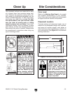
1. Unfold the two stand leg assemblies. They
are hinged on the edges for easy set up.
2. Using the M6-1 hex nuts, hex bolts and flat
washers, install the corner support braces
in the bottom corners of the leg assemblies
(Figure 5).
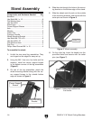
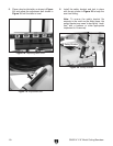
3. On one of the leg assemblies, attach the
wheel mounting bracket along with the cor
-
ner support braces to the outside bottom
edge as shown in
Figure 5.
6. On the other leg, Insert the handle into the
pre-drilled holes and secure with the cotter
pins (see
Figure 7).
Figure 5. Corner braces and wheel bracket.
Wheel Mounting
Bracket
Corner Support
Braces
Figure 7. Cotter pins installed into
the handle.
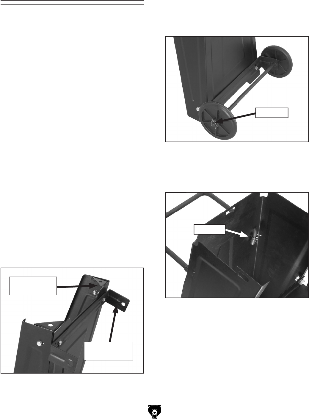
Figure 6. Wheel assembly.
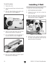
Cotter Pin
4. Slide the axle through the holes in the mount-
ing bracket on the bottom edge of the stand.
5. Slide the wheels onto the axle on the outside
of the mounting brackets, and secure with the
cotter pins as shown in
Figure 6.
Cotter Pin