


Model G0758 (Mfd. Since 2/14)
-25-
Installing/Removing
To olin g
Cutting tools are sharp and
can easily cause cutting
injuries. Always protect
your hands with leather
gloves or shop rags when
handling cutting tools.
Installing Tooling
Tools Needed Qty
Spindle Pin ........................................................ 1
Wrench 8mm ..................................................... 1
To install tooling:
1. DISCONNECT MACHINE FROM POWER!
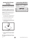
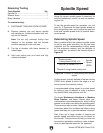
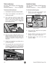
2. Remove drawbar cap (see Figure 27).
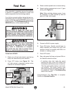
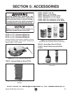
Figure 28. Components used when installing or
removing tooling.
Drawbar
Drawbar
Adjustment
Nut
Spindle Pin
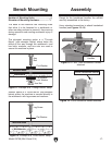
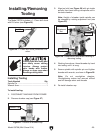
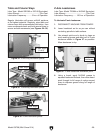
The Model G0758 includes a 1–13mm drill chuck
with R-8 arbor (see Figure 26).
Figure 26. 1–13mm drill chuck joined with R-8
arbor.
Figure 27. Location of drawbar cap.
Drawbar Cap
3. Align tool slot (see Figure 26) with pin inside
spindle, then insert tooling into spindle until in
contacts drawbar.
Note: Height of drawbar inside spindle can
be changed by rotating adjustment nut (see
Figure 28).
4. Working from above, thread drawbar by hand
into tooling until it is snug.
5. Secure spindle with spindle pin and tighten
drawbar with wrench, as shown in Figure 28.
Note: Do not overtighten drawbar.
Overtightening makes tool removal difficult
and will damage arbor and threads.
6. Re-install drawbar cap.
Tool Slot