


-13-
G1006/G1007 Mill/Drill
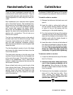
Handwheels/Crank
There are three handwheels provided with the
machine which control table movement. They are
secured with setscrews and mounted as follows.
Height adjustment is made using the crank pro-
vided.
Each handwheel has a setscrew which tightens
with a 3mm Allen
®
wrench. The handwheel han-
dles screw into the threaded holes on each hand-
wheel. Turn the nut on the handwheel handles
until almost tight against the plastic handle.
Screw into the handwheel and tighten the nut
against the wheel while maintaining the screw’s
position with a screwdriver. This nut acts as a
locknut and a spacer.
The first two handwheels mount on the ends of
the table and move the table left and right. With
the power feed installed on the G1007, there is
only one side handwheel installation location.
Save the extra handwheel in case the power feed
cannot be used.
The third handwheel mounts in front of the base
and moves the table toward and away from the
front of the machine.
The head crank secures to the left side of the
machine. Screw its handle into the threaded hole
at the end of the crank. This handle is similar to
those in the handwheels. Use a 5mm Allen
®
wrench to tighten the setscrew that secures the
hand crank to its shaft.
Screw a black knob onto an end of each of the
three chrome feed levers. These are the levers
that control the up and down movement of the
spindle. Screw the levers with knobs into the
threaded holes on the hub, located on the right
side of the machine.
Collet/Arbor
The Models G1006/G1007 feature an R-8 spindle
which accepts many industrial collets and arbors.
To install a collet or an arbor:
1. Release the latches on the head cover and
open it.
2. Insert the collet or cutting tool’s arbor up
into the spindle housing. Rotate the collet
or arbor to line up the keyway with the
matching pin in the spindle opening.
3. Turn the hex head at the top of the drawbar
(located on the top, front of the head) clock-
wise until the threads at the bottom of the
drawbar mesh with the female threads in
the top of the collet or arbor.
4. Insert the cutter in the hole at the bottom of
the collet and continue to tighten the draw-
bar until both the collet and cutter are tight-
ly in place. Do not over-tighten the collet.
Grasp the V-Belt that goes around the
front pulley. Pull gently while tightening.
To remove a collet or an arbor:
1. Loosen the hex head at the top of the draw-
bar (2 or 3 turns).
2. Hold the cutter with a shop towel to pre-
vent it from dropping completely out of
the machine. Tap on the top of the draw-
bar with a rubber mallet to loosen the collet
from the spindle.
3. Continue to turn the drawbar counterclock-
wise until it is free from the collet. Once
loose, remove and replace with your
desired collet. Remove cutting tools from
spindle when not in use.