


-10- G1013 Combination Sander
SECTION 4: ASSEMBLY
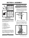
Overview
The majority of your Combination Sander has
been assembled at the factory. The few remain-
ing pieces will go together quickly and should be
done in the following order:
1. Feet to Base
2. Sanding Unit to Base
3. Table Support to Base
4. Motor to Base
5. Motor Pulley to Motor Shaft
6. V-Belt to Pulleys
7. Belt Guards to Sanding Unit
8. Aluminum Disc to Motor Shaft
9. Tables to Sanding Unit
10. Wiring motor
Only a few common tools are required to assem-
ble your Combination Sander. Specifically, these
are: 6" adjustable wrench, 10mm open end
wrench, 12mm open end wrench, Phillips
®
head
screwdriver, 3mm Allen
®
wrench (supplied with
machine), and a rubber mallet.
Some metal parts may
have sharp edges on
them after they are
formed. Please examine
the edges of all metal
parts before handling
them. Failure to do so
could result in injury.
Assemble as follows:
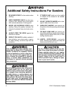
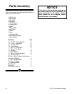
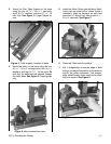
1. Attach the four (4) rubber feet to the base
using the four (4)
1
⁄4" - 20 x 1" hex bolts, four
(4)
1
⁄4" flat washers and four (4)
1
⁄4" - 20 hex
nuts. Be sure that the bolts protrude upward
through the base. See Figure 3.
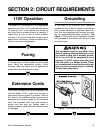
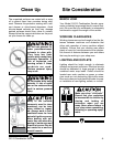
Figure 4. Sanding unit mounted on base.
Figure 3. Order of foot attachment.
2. Place the preassembled Sanding Unit onto
the Base as shown in Figure 4. Secure with
the four (4)
5
⁄16" - 18 x
3
⁄4" hex bolts, eight (8)
5
⁄16" flat washers, and four (4)
5
⁄16" - 18 hex
nuts.
Assembly Process
Do not connect power to
the machine when per-
forming any assembly.
Failure to do this may
result in serious person-
al injury.