


-12- G1013 Combination Sander
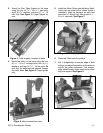
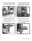
Figure 9. Belt guard attached to sander.
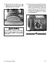
Figure 10. Belt table attached to sander.
9. Attach the belt guards as shown in Figure 9.
Secure with four (4) M5-0.8 x 6mm Phillips
®
head screws and 5mm washers.
10. Install the belt table using the
5
⁄16" - 18 x
5
⁄8"
carriage bolt,
5
⁄16
" fender washer and
5
⁄16
" - 18
hex nut. See Figure 10.
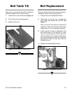
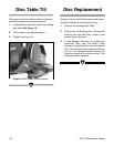
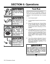
Figure 12. Disc table attachment.
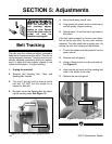
11. Slide the 8'' aluminum disc onto the motor
shaft. Lightly tap into place with a rubber
mallet if necessary. Align the disc and motor
shaft keyways and insert the
3
⁄16'' square key.
Secure the disc with a
1
⁄4" - 20 x
3
⁄8'' setscrew.
See Figure 11.
Figure 11. 8" disc attached to motor.
12. Peel the backing from the new sanding disc
paper and stick it to the Aluminum Disc.
13. Secure the Disc Table to its support bracket
using the two (2)
1
⁄4
" - 20 x 1
1
⁄4
" carriage
bolts, two (2)
1
⁄4" flat washers and two (2)
1
⁄4"
- 20 wing nuts. See Figure 12.
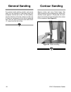
8. Move the motor back to set the belt tension.
The belt should deflect about
1
⁄2" per side
when squeezed in the middle with moderate
pressure. Tighten the motor down when ten-
sion is correct.