


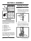

G1013 Combination Sander -11-
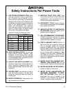
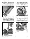
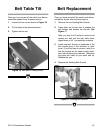
Figure 5. Table support mounted on base.
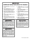
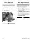
Figure 6. Motor mounted on base.
3. Attach the Disc Table Support to the base
using the four (4)
5
⁄16" - 18 x 1
1
⁄4" hex bolts,
eight (8)
5
⁄16" washers, and four (4)
5
⁄16" - 18
hex nuts. See Figure 5. Finger tighten for
now.
4. Mount the Motor to the base using the four
(4)
5
⁄16" - 18 x
5
⁄8" carriage bolts, four (4)
5
⁄16"
washers, and four (4)
5
⁄16" - 18 hex nuts. Be
sure that the bolts protrude upward through
the motor base. See Figure 6. Finger tighten
only.
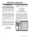
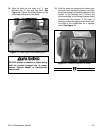
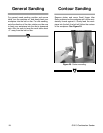
Figure 8. Inspecting pulley alignment.
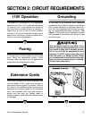
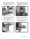
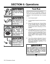
Figure 7. Motor pulley attachment.
6. Place the V-Belt onto the pulleys.
7. Set a straightedge across the edge of both
pulleys and adjust the position of the motor to
correct the pulley alignment. The straight-
edge should evenly touch each pulley when
they are aligned. See Figure 8.
5. Install the Motor Pulley onto the Motor Shaft.
Lightly tap into place with a rubber mallet if
necessary. Align the keyways on each and
insert the
3
⁄16'' square key. Secure with a
1
⁄4" -
20 x
3
⁄8'' setscrew. See Figure 7.