


-1 2 -
-12-
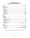
Gear Ranges – Model G1126
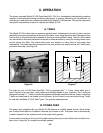
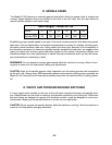
D. SPINDLE SPEED
The Model G1126 features an internally-geared head which offers six speeds, both in forward and
reverse. Speed selection levers are located on the front of the mill head. See the chart below for
specific spindle speeds in each gear range.
Levers L1 L2 L3 H1 H2 H3
Spindle RPM 60 130 230 450 800 1500
REMEMBER: Do not attempt to change gear speeds while the machine is running. Allow all mov-
ing parts to come to a full stop before making any adjustments.
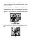
E. ON/OFF AND FORWARD/REVERSE SWITCHING
A 3-way toggle switch located on the front of the mill head controls both power and spindle direc-
tion. Always make sure the cutter is rotating in the direction required by your cutting tool. While most
bits and cutters are designed to operate in a clockwise rotation, some are designed to work coun-
terclockwise. Make sure the spindle direction is correct for your application.
CAUTION: Do not reverse the spindle direction while the machine is running. Allow the machine to
come to a full stop before changing directions.
CAUTION: Even at low spindle speeds, metal fragments from the cutting process can be expelled
by the mill / drill. Always wear ANSI-approved eyewear and protective clothing when operating the
Model G1126. Be sure that all observers are safely away from the machine while it is being operat-
ed.
Establishing proper spindle speed is just part of the same complex equation that determines power
feed rates. Like we noted before, the equation encompasses a number of variables, including; spin-
dle speed, metal hardness, feed rate, cutting depth and cutter type. Because of the complexity of
the equations necessary to determine optimum spindle speeds and feed rates, we suggest once
again you obtain one of many good machinist’s guides on the market. Community colleges and
vocational schools are often good places to obtain informative textbooks which go into the neces-
sary mathematics of machining in detail.