


-1 3 -
-13-
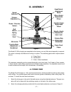
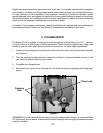
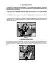
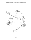
Figure 9
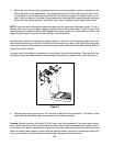
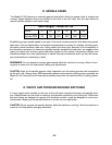
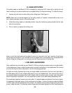
G. DOWNFEED LIMITER
The downward movement of the spindle assembly can be limited by using the adjusting knob
mounted on the forward portion of the feed base, just below the depth stop gauge on the front of the
mill head. See Figure 10. Limiter distance can be set by using the indicator on the front of the milling
head.
Figure 10
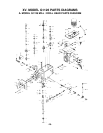
F. SPINDLE HEIGHT
The Model G1126 uses rack-and-pinion gearing to control spindle height adjustment. The operator
has two options for adjustment – a 3-handled downfeed control and a handwheel-operated micro
adjustment control. See Figure 9.
To operate the micro-adjustment handwheel, tighten the locking knob on the 3-handled downfeed
control. Once locked, the adjustment of spindle height will be transferred to the handwheel.
The calibration dial can be adjusted for individual applications by loosening the setscrew on the
knurled surface and turning the indicator to “zero out” the dial. Once in place, tighten the setscrew.
A certain amount of backlash or play is typical in pinion gearing so keep in mind, while setting the
measurement dial, to make your adjustments while there is downward pressure against the micro
adjustment handwheel.