


-10- G1183/1276 Combination Sander
SECTION 4: ASSEMBLY
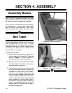
Assembly Basics
Belt Table
The belt table adjusts to allow you to sand your
work at angles from -30° up to 45°. To make
assembly easier, we recommend you mount the
Combination Sander on a table or bench before
assembling. Four bolt holes are included on the
sander’s base for mounting.
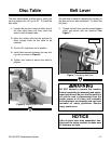
To attach the belt table:
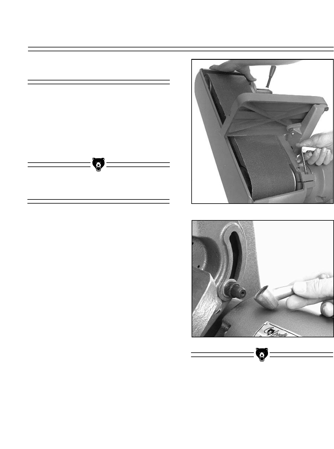
1. Swing the belt assembly to its vertical posi-
tion by loosening the 6mm Allen
®
capscrew
shown in Figure 4. Tighten capscrew to
hold the belt assembly in this position.
2. Remove the lock handle assembly and the
threaded stud from the belt housing using a
large flat bladed screwdriver.
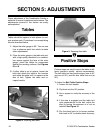
3. Line up the belt table trunnion with the slot
in the belt assembly bracket. Reinstall the
threaded stud, then install the flat washer,
toothed nut, lock handle, lock washer and
bolt, as shown in Figure 5. Make sure the
handle is installed so the table can be loos-
ened and tightened without interfering with
other components. The belt table’s tight fit
is deliberate. Placing the table in position is
easier if you swing the belt table so the 45°
positive stop bolt is located over the gap in
the motor casting cover.
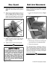
Figure 4. Attaching belt table.
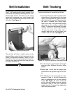
Figure 5. Installing lock handle.
Most of your Combination Sander has been
assembled at the factory. There are several sim-
ple steps to follow to complete the assembly.
A few common tools will be required for assem-
bly: Screwdrivers - medium and large straight
blade or Phillips
®
, Allen
®
wrenches - 2mm, 3mm,
6mm and open end wrenches - 8mm and 10mm.