-13-
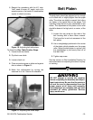
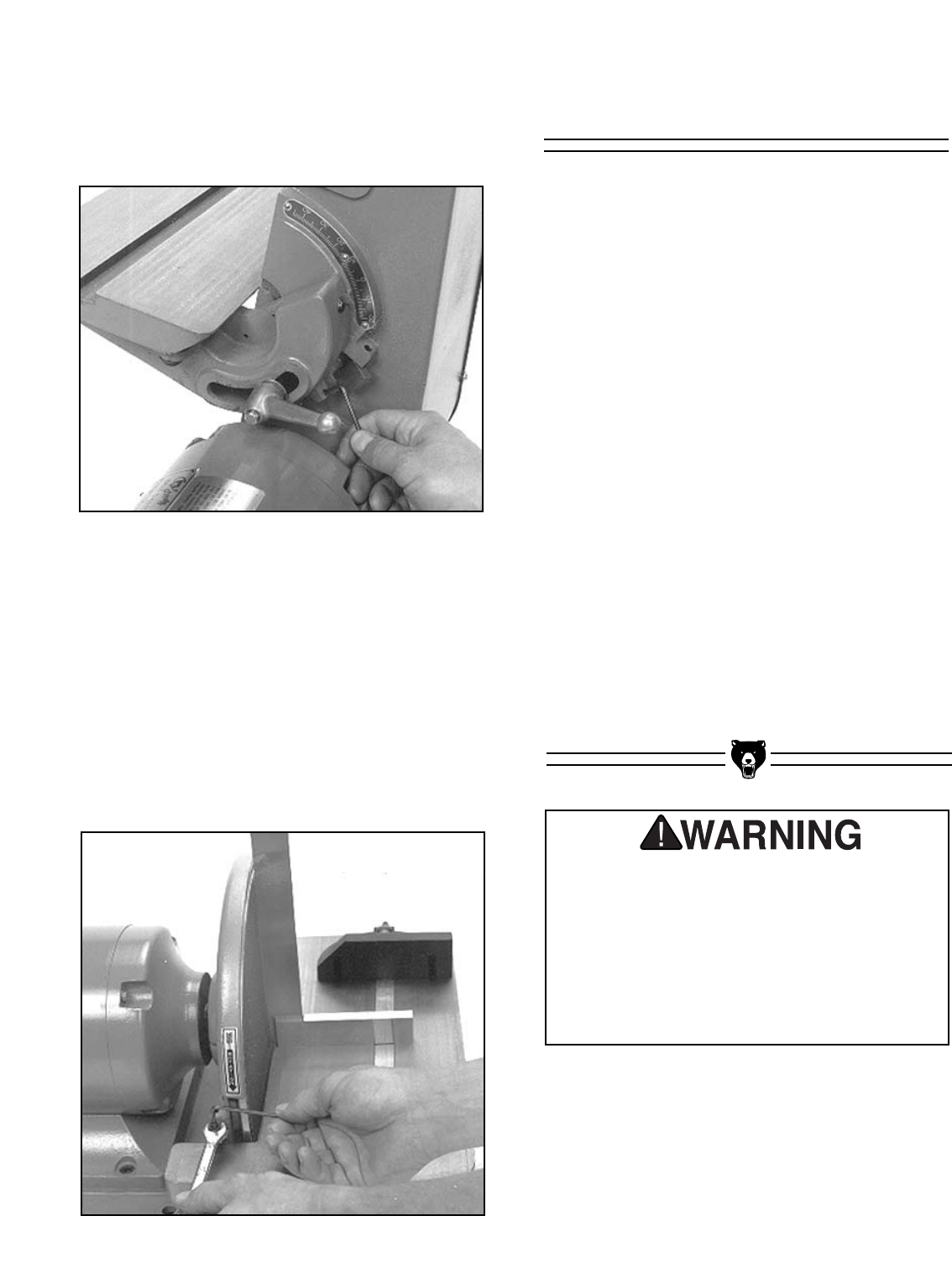
Figure 11. Adjusting disc table stops.
G1183/1276 Combination Sander
6. Repeat this procedure with the 45° stop.
You’ll need a known 45° angle, such as a
speed square or the head of a combination
square to check accuracy.
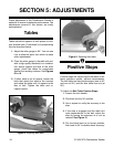
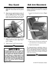
Figure 10. Adjusting belt table stops.
To Adjust the Disc Table Positive Stops:
1. Loosen both star knobs.
2. Flip block over table.
3. Loosen check nut.
4. Place accurate square on table and against
disc as shown in Figure 11.
5. Make fine adjustments by turning the
setscrew in or out. Secure the checknut.
Belt Platen
DO NOT attempt to operate this machine
before completing the assembly and adjust-
ment instructions. Be sure that the switch is
off and the cord is disconnected from the
power source at all times until assembly
and adjustment are complete and you have
reviewed all safety guidelines. Serious
injury could occur.
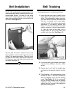
The belt platen should be adjusted out far enough
so it is flush with, or slightly higher than the upper
roller. The rollers are slightly crowned, that is they
are higher in the center than at the edges. This
crowning helps the belt to stay centralized on the
rollers. The adjustment of the platen to the roller
should be done at the high point, or center, of the
roller.
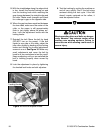
1. Loosen the cap screw on the side of the
belt housing with a 6mm Allen
®
wrench.
This frees the in and out movement of the
belt platen
2. Use a straightedge positioned in the center
of the platen which extends over the upper
roller. Adjust the belt platen in and out until
the straightedge is just barely lifted off of
the idler roller.
3. Tighten cap screw.
See the section on Belt Installation/Tracking for
more information on adjusting the rollers for prop-
er tracking.


