


-14- G1183/1276 Combination Sander
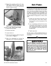
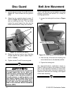
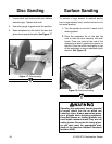
1. Loosen the two screws (A and B) shown in
Figure 12. These screws hold the guard in
place.
2. Adjust the two vertically-aligned screws (C
and D in Figure 12) so the guard is upright
and not touching the disc. The top screw
moves the guard toward the disc and the
bottom screw moves it away from the disc.
Disc Guard
Figure 12. Adjusting disc guard.
A
B
C
D
3. Rotate the disc by hand to see if the disc
scrapes against the guard; repeat Steps 1
and 2, if needed.
4. Tighten screws C and D to secure guard.
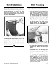
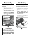
Belt Arm Movement
The 6" x 48" Belt Arm can be locked at any angle
between horizontal and vertical for a variety of
sanding applications.
1. Loosen the locking bolt as shown in Figure
13.
Figure 13. Loosening belt arm locking bolt.
2. Grab the top of the belt arm housing and
move the belt arm to the desired position.
3. Tighten the locking bolt.
The setscrew/checknut combination shown in
Figure 13 acts as a stop for the rotation of the belt
arm. If it ever becomes necessary to remove the
belt arm from the motor, be sure to remove this
setscrew to allow the arm housing to be slipped
of the motor mounting.
Operating this equipment has the potential
to propel debris into the air which can
cause eye injury. Always wear safety glass-
es or goggles when operating equipment.
Everyday glasses or reading glasses only
have impact resistant lenses, they are not
safety glasses. Be certain the safety glass-
es you wear meet the appropriate stan-
dards of the American National Standards
Institute (ANSI).
Rotation Stop Setscrew