


-20- G4002/3 Gear Head Lathes
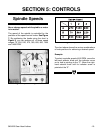
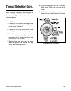
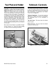
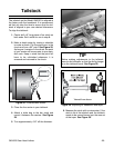
Figure 21. Spindle rotation control lever.
Spindle rotation control - The spindle rotation is
controlled from the lever on the right hand side of
the carriage. Moving the lever down causes the
spindle to rotate counter clockwise. Moving the
lever up causes the spindle to turn clockwise. The
middle position stops the motor and the lever is
considered to be in a neutral position. See Figure
21.
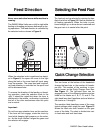
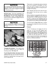
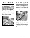
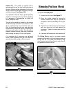
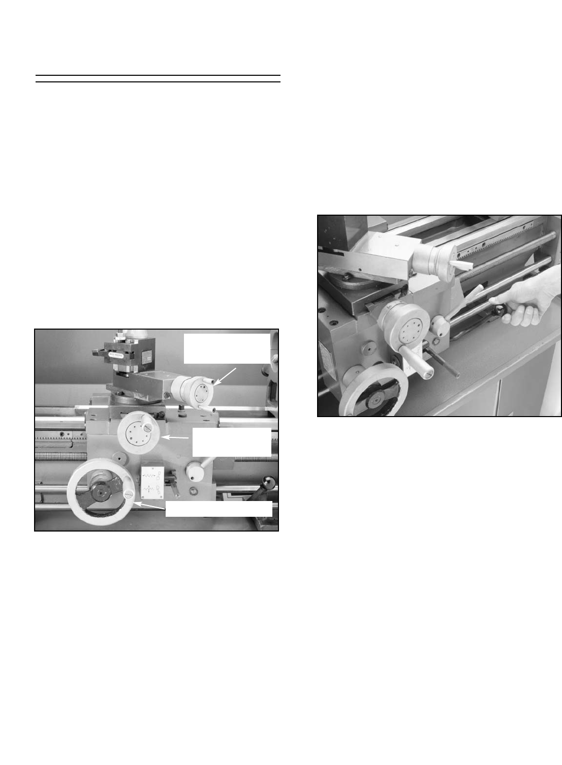
Figure 20. Handwheel locations.
Carriage Controls
The carriage handwheel allows the cutting tool to
move along the length of the lathe bed. The
cross slide allows the cutting tool to travel per-
pendicular to the bed. The carriage features a top
slide which allows linear movement of the cutting
tool at any preset angle. This section will review
the individual controls on the carriage and pro-
vide descriptions of their uses. See Figure 20.
Compound Slide Handwheel - The Top Slide
Handwheel controls the position of the cutting
tool relative to the workpiece. The top slide is
adjustable for any angle. The graduated dial is
adjustable using the same method as the dial on
the cross slide. Angle adjustment is controlled by
hex nuts on the base of the top slide.
Cross Slide Handwheel - The Cross Slide
Handwheel moves the top slide toward and away
from the work. Turning the dial clockwise moves
the slide toward the workpiece. The graduated
dial can be adjusted by holding the handwheel
with one hand and turning the dial with the other.
Carriage Handwheel - The Longitudinal
Handwheel moves the carriage left or right along
the bed. The control is helpful when setting up the
machine for turning or when manual movement is
desired during turning operations.
Carriage Handwheel
Cross Slide
Handwheel
Compound Slide
Handwheel