G8622 Tilting Spindle Sliding Table Shaper -13-
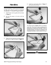
Handles
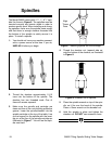
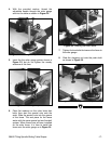
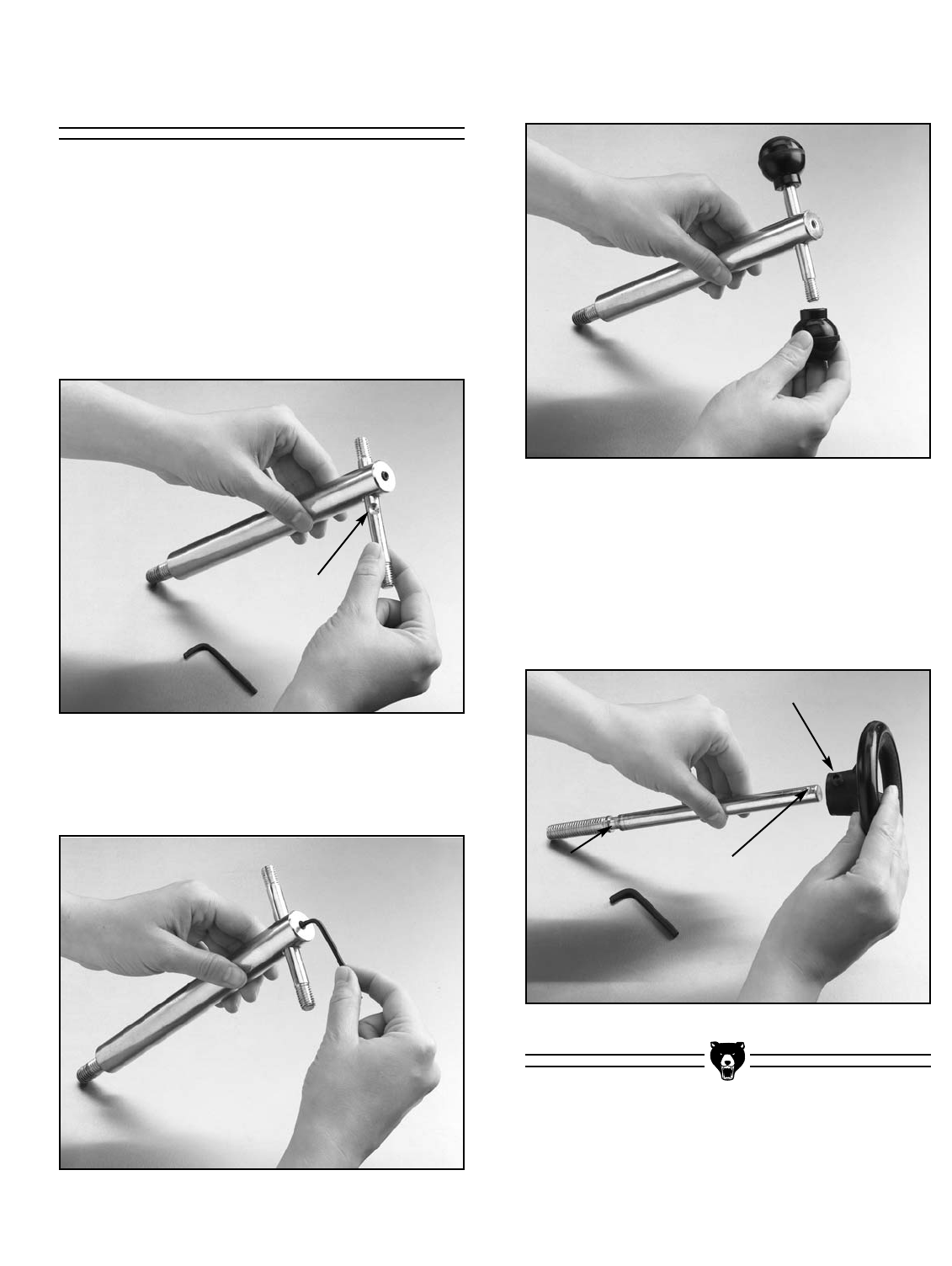
Figure 9. Slide bar into guide shaft.
Figure 11. Thread round knobs onto bar.
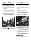
Figure 12. Installing wheel onto adjustment guide.
Figure 10. Tightening setscrew with hex key.
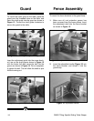
The guard adjuster is used to secure the guard to
the table and to allow the guard to be loosened
for adjustment. To assemble the guard adjuster:
1. Install the bar into the guide shaft as shown
in Figure 9.
2. Line up the groove in the bar with the
setscrew.
Groove
Setscrew Groove
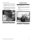
3. Tighten the shaft setscrew into the groove to
lock the bar in place as shown in Figure 10.
4. Install the round knobs shown in Figure 11
onto both ends of the bar.
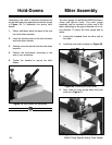
The wheel shown in Figure 12 fits on the adjust-
ment shaft. This locks in place by tightening the
setscrew into the groove on the shaft. There is a
threaded hole on the wheel that allows for the
optional installation of a crank (not included). The
completed assembly is used to adjust the fence.
Setscrew
Shaft
Groove


