


-10- H3114 Router Table
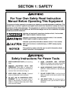
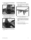
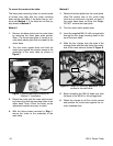
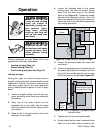
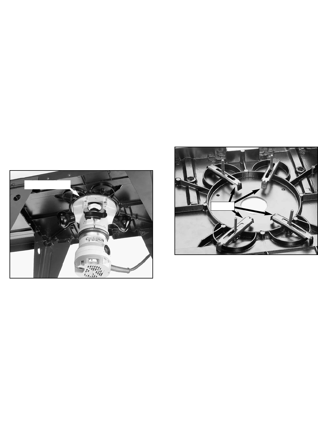
Figure 7. Router positioned correctly for
"Method 1" installation.
3. Rotate the router until the main table mount-
ing holes align with the mounting holes in the
router base. Note—Orient the router so the
adjustment controls are easy to reach.
4. With the three screws removed in Step 1,
secure the router to the underside of the
main table.
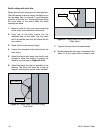
Method 2
1. Remove the base plate from the router base.
Note–The bottom face of the router base
must form a continuous ring with no gaps. If
the router base does not have this design,
DO NOT remove the base plate.
2. Turn the router table upside down.
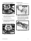
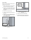
3. Insert the supplied M5-0.8 x 45 carriage bolts
through the four large mounting holes in the
top of the main table.
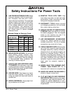
4. Slide the four clamps over the ends of the
carriage bolts with the tabs facing the under-
side of the main table as shown in Figure 8.
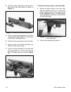
5. Begin threading the M5-0.8 keps nuts onto
the ends of the M5-0.8 x 45 carriage bolts.
6. Rotate the clamps out of the circular recess
and position the router base against the cir-
cular recessed area.
Figure 8. Clamps for securing “Method 2” style
routers to the main table.
To mount the router to the table:
The base plate mounting holes on some brands
of routers may align with the router mounting
holes on the main table. If the holes line up, con-
tinue with Method 1. If the holes do not line up,
skip ahead to Method 2.
Method 1
1. Remove the base plate from the router base
by removing the three base plate screws.
Note—The router base plate is usually a cir-
cular black plastic plate that is screwed to the
router base.
2. Turn the router upside down and hold the
router base against the circular recess in the
underside of the main table as shown in
Figure 7.
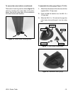
Circular Recess
Clamps