


-12- H3114 Router Table
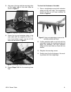
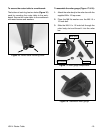
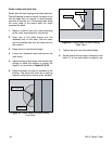
Figure 13. Installing the pocket jointing fence.
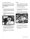
Figure 14. Securing the fence to the main table.
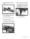
3. Slide the pocket jointing fence into the slot in
the face of the main fence as shown in
Figure 13.
4. Secure the pocket jointing fence to the main
fence with the supplied M8-1.0 x 20 hex bolt
and the M8-1.0 threaded knob.
5. Place the fence assembly on the main table.
6. Align the slots on the fence assembly over
the slots on the table surface.
7. Secure the fence assembly to the table with
the supplied M8-1.0 x 40 hex bolts and the
M8-1.0 threaded knobs as shown in Figure
14.
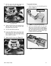
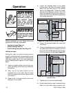
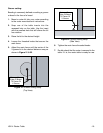
Figure 15. Securing the power switch
to the main table.
2. Flip the table assembly top-side up
.
To attach the power switch to the main table:
1. Secure the power switch to the main table
with the supplied #10-32 x
3
⁄4" truss head
phillips screws and the #10-32 keps nuts as
shown in Figure 15. Note—The power switch
mounting bracket should be on the inside of
the main table edge.