


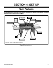
H3114 Router Table -11-
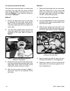
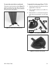
Figure 11. Correct spring placement.
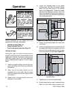
Figure 12. Correctly installed guard.
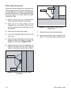
Figure 10. Correctly clamped router.
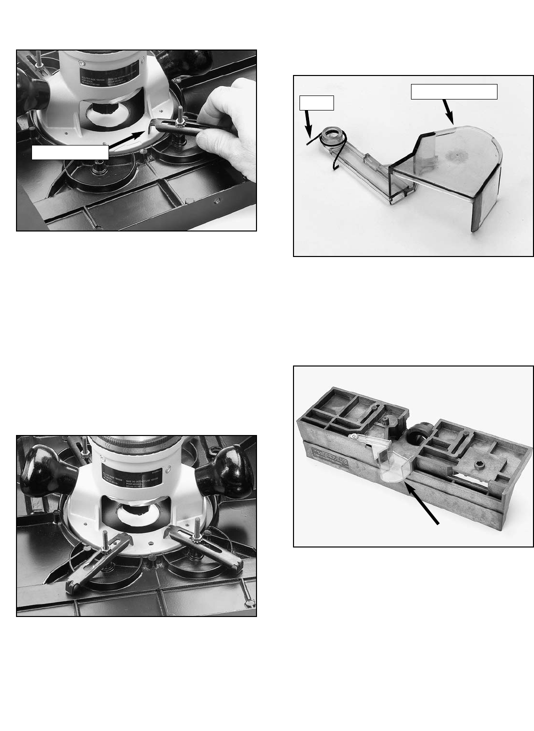
2. Insert the retractable guard into the fence
and secure the guard with the supplied M4 x
12 tap screw and the M5 flat washer (Figure
12). The bit guard should move freely with no
binding on the fence. If binding occurs, light-
ly sand or file the contact areas.
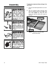
To assemble the fence:
1. Attach the spring to the retractable guard as
shown in Figure 11.
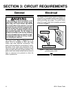
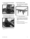
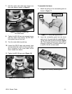
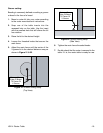
7. Hold the router and rotate the clamps over
the router base as shown in
Figure 9
.
8. Tighten the M5-0.8 keps nuts enough to pre-
vent the router from moving, but DO NOT
fully tighten them at this time.
9. Turn the router table top-side up.
10. Loosen the M5-0.8 keps nuts several turns
and reposition the router until the router spin-
dle is centered in the round table cut-out
when viewed from above.
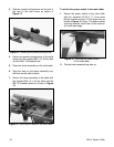
11. Tighten the M5-0.8 keps nuts (
Figure 10
).
Figure 9. Rotating a clamp over
the router base.
Spring
Retractable Guard
Clamp Position