


SKU 05154 PAGE 11
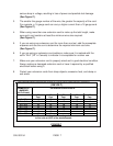
27. WARNING! The warnings, precautions, and instructions discussed in this
manual cannot cover all possible conditions and situations that may occur. The
operator must understand that common sense and caution are factors which
cannot be built into this product, but must be supplied by the operator.
ASSEMBLY AND OPERATING INSTRUCTIONS
NOTE: For additional references to the parts listed in the following pages, refer to the
Assembly Diagram on page 20.
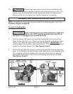
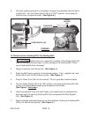
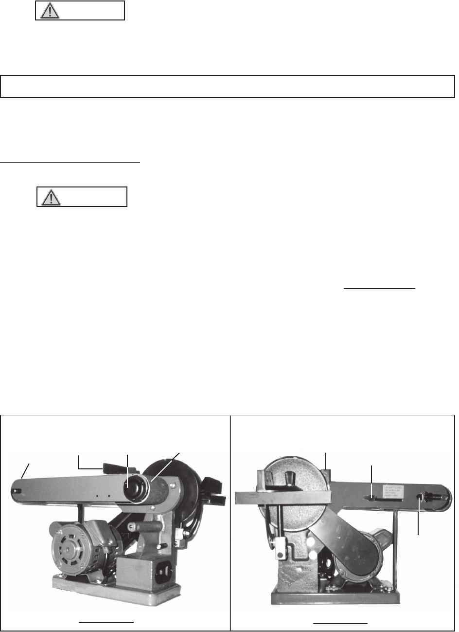
To Install A Sanding Belt:
1. WARNING! Prior to performing any assembly procedures, make sure
the Power Switch (30) is in its “OFF” position and the Power Cord (29) of
the Sander is unplugged from its electrical outlet.
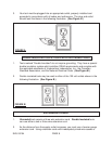
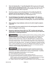
2. Push the Handle (36) forward, and slide the Sanding Belt (45) onto the Drive
Roller (5) and Idler Roller (41). Make sure the Sanding Belt is centered on both
Rollers. Then, slide the Handle back to its original position. IMPORTANT: To
avoid damage to the machine, make sure there is a 1/16” gap between the Sand-
ing Belt and the Work Support (33) (See Figures E and F.)
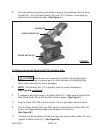
3. With the Sanding Belt (45) installed, rotate the Sanding Belt a few revolutions by
hand. If the tracking of the Sanding Belt needs adjusting, turn the Adjusting Knob
(39)
clockwise
to make the Sanding Belt track more to the
right
. To make the
Sanding Belt track more to the
left
, turn the Adjusting Knob
counterclockwise
.
(See Figures E and F.)
ADJUSTING
KNOB
(39)
HANDLE
(36)
IDLER
ROLLER
(41)
DRIVE
ROLLER
(5)
SANDING
BELT
(45)
FIGURE E
WORK
SUPPORT
(33)
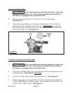
WORK
SUPPORT
(33)
FIGURE F