


Before adjustments are made, ensure that the machine is SWITCHED OFF AND UNPLUGGED. Also make sure all locking
handles and securing screws are FULLY TIGHTENED when adjustments are completed.
Before assembling, remove all traces of preservative from the components and wipe all parts thoroughly with a clean dry cloth.
Apply a thin coating of light machine oil to the table, column and base to prevent rust.
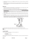
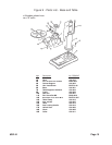
Column Assembly to Base
MOUNTING SURFACE: Ideally, the base should be firmly bolted to the floor or workbench prior to assembly of other compo-
nents. The mounting surface must be flat, level and capable of supporting the drill press’weight combined with materials to be
drilled. Mount the drill at a sufficient height so you need not bend your back to operate.
1. With the Base on a flat level surface, bolt on the Column Support (#4B) using the five 10 x 40mm hex head screws provided.
2. Tighten firmly.
Table and Support Arm to Column
1. Remove the rack (#2B) from the column by slackening off the collar grub screw (#11B) and removing the collar (#19B). The
rack is stowed in this position for transit purposes.
2. Lubricate the worm gear (#18B) with light grease, and insert it shaft first fully into its housing in the arm until it is flush with
the helical gear (#17B). Hold it in this position. The worm gear shaft will extend through the housing ready for the crank to
be attached later.
3. Gently slide the arm assembly over the column and hold it steady while inserting the rack down through the worm gear
housing until it is flush with the helical gear, ensuring the long smooth end of the rack faces up. Place the bottom end of the
rack in the groove formed by the column support and the column.
4. Hold in this position while replacing the collar on the column. Ensure that the end of the rack is firmly engaged in the groove
formed between the collar and the column. However, there must be a working clearance between the rack and collar —
make sure the rack is not pinched. Firmly secure the collar with the grub screw.
5. Thread the Arm Locking Handle (#16B) in from the left, and tighten to secure the arm to the column.
6. Attach the table crank (#8B) to its spigot and tighten the securing screw.
7. Slacken off the arm locking handle and turn the crank, testing to ensure the arm will move the full length of the rack easily,
without binding, and will also rotate about the column evenly and without tight spots. Note: If too tight, nip up the arm
locking handle and slacken off the collar grub screw. Adjust to give a greater working clearance between the rack and
collar, tighten the grub screw and test again.
8. Insert the table into its housing on the arm and secure with the table clamp (#13B).
Head to Column
1. It may be necessary to unscrew the Head Lock Set Screws (#21A) slightly to ensure they do not protrude internally, as this
will prevent the head from sliding fully into position.
2. With assistance, raise the Head and place it on top of the Column, ensuring it slides home fully.
3. Align the head with the base and firmly secure with the Set Screws (#21A) provided.
4. Screw the three Feed Handles (#24A) and screw them firmly into the hub of the spindle feed shaft (#25A).
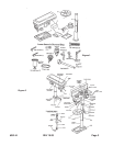
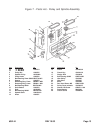
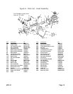
Assembly (Please refer to Figure 2 and Parts Lists/Diagrams)
CAUTION! Consider the weight of the components and take necessary precautions when lifting components. Assistance
will be required when assembling.
#38144 Page 6