


Before adjustments are made, ensure that the machine is SWITCHED OFF AND UNPLUGGED. Also make sure all locking
handles and securing screws are FULLY TIGHTENED when adjustments are completed.
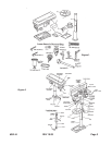
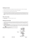
TO ADJUST THE TABLE
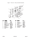
The table is capable of moving in four directions (see Figure 3).
1. Raise or lower the table by slackening off the arm locking handle (A) and turning the crank (C) CLOCKWISE TO RAISE and
COUNTER CLOCKWISE TO LOWER.
2. Swivel the table about the column by slackening off the arm locking handle. The table assembly, arm and rack (B) move in
unison around the column.
SETTING THE REQUIRED ANGLE (see Figure 3)
1. Tilt the table by slackening the Bevel Table Locking Screw (E) and tilting to the required angle. A scale (F) is provided on
the arm measured in degrees, to assist in setting the required angle. For all normal operations, the table should be set to
0 degrees.
2. To ensure the drill is entirely perpendicular to the table, insert a piece of straight round bar in the chuck, place a square on
the table and bring it up to the round bar. Adjust the table tilt if necessary so that the table is correctly aligned.
3. Turn the table about its axis by slackening off the clamp (D).
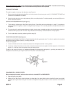
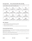
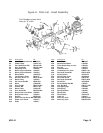
TO SET DRILLING DEPTH (See Figure 4)
Located around the Spindle Feed Shaft is a Depth Stop Collar (A) with a graduated scale. The collar is capable of turning about
the shaft and can be locked in place by a Locking Screw (B).
To set a drilling depth:
1. Lower the Chuck until the drill contacts the surface of the workpiece and hold it in that position.
2. Loosen the Locking Screw and turn the collar so that the measurement for the depth of the hole required is in line with the
pointer (C). Lock the collar in this position using the locking screw.
The drill is now set to drill holes to your predetermined depth from that particular start point (i.e., providing the surface of your
workplace is flat and level, you may drill a series of holes, each to the same depth).
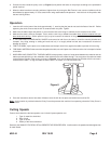
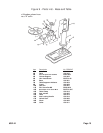
CHANGING DRILL (SPINDLE) SPEED
Before changing the speeds, make sure the machine is switched OFF and UNPLUGGED.
1. Open the pulley cover (#23).
2. Slacken off the Belt Tension Locking Knobs (on either side of the head #18A) and turn the Belt Tension Lever (#19A)
clockwise to bring the Motor Pulley (#11A) closer to the Spindle Pulley (#3) in order to remove all tension from the drive
belts.
Figure 4
#38144 Page 8