


Installing the Chuck
1. With the Chuck Guard lifted clear of the spindle nose, slide the work table up the column to within 6” of the spindle.
2. Open the jaws of the chuck to their maximum width, using the Chuck Key supplied.
3. Put a piece of scrap wood on the table to protect the Chuck Nose.
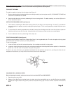
4. Ensuring all parts are thoroughly clean and dry and burr free, insert the arbor (#14) firmly into the end of the chuck. The
other end of the arbor, with the chuck now attached, is then inserted into the end of the spindle shaft (#13) turning, where
necessary, to ensure the tang on the end of the arbor is aligned correctly with the drive slot in the spindle shaft. Pull the
spindle down using the feed handles, pressing the chuck jaws hard against the piece of scrap wood until the chuck is forced
home.
Pulley Cover Knob
1. Locate the knob with pan head screw and attach to the cover.
2. Screw on tightly.
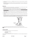
Installing the Drive Belt
1. Undo the Belt Tension Locking Knobs (one either side of the head #18A) and turn the Belt Tension Lever (#19A) clockwise
to bring the motor pulley (#11A) closer to the spindle pulley (#3) which will allow the belts to be slipped on with ease.
2. Lubricate the Idler Pulley Pivot shaft (#20) and Idler Pulley with light grease and install in its mounting between the motor
and Spindle Pulleys.
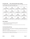
3. Consult the chart inside the pulley cover (and duplicated in this manual) and install the belts in the positions corresponding
to spindle/drill speed required.
4. Turn the belt counterclockwise so that tension is applied to the belts. Tension is correct when the belt deflects by approxi-
mately 1/2” at their centers of run when using reasonable thumb pressure. Lock the motor in this position using the locking
screw. Note: If the belt slips during operation, adjust the belt tension.
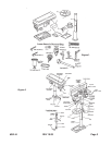
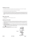
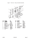
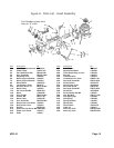
Settings and Adjustments (Please refer to Figure 3)
Figure 3
#38144 REV 10/03 Page 7