


SKU 42827 For technical questions, please call 1-800-444-3353. Page 7
BASIC OPERATION
Prior to Operation
1. Check the oil level, and if necessary ll to the mid point of the oil level window.
Basic Controls
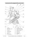
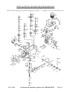
Please refer to Figure 1 on page 5.
1. Raise and lower the Head by using the Head Crank (#4).
2. Feed the Spindle using Spindle Feed Handle (#16). Precise movements may be made using the
Spindle Micro Feed Handle (#15).
3. Move or feed the table from side to side by using the Table Feed Wheel (#7).
4. Move the Table front to back using the Cross Table Feed Wheel (#13).
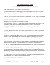
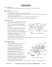
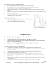
Adjusting the Head
1. To raise or lower the head, loosen the 2 heavy
duty head lock nuts shown in the left part of
Figure 3. Use the left side head handle to
raise or lower the head on its rack and pinion
mechanism.
2. The head may be rotated 360
O
by loosening
the same bolts mentioned in item 1. Adjust
the head to the desired angle, then x the
heavy-duty head lock nuts. Periodically check
the tightness of these nuts, especially during
prolonged use of the machine.
3. To set the head at an angle, loosen the three
nuts shown in the right part of Figure 3.
Retighten the nuts when you have set the angle at the desired degree. Refer to the scale on the
right side of the head to read the angle.
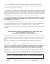
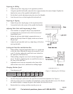
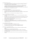
Preparing for Drilling
Please see Figure 4.
1. Rotate the knob in the center of the spindle
feed handle (#16) counterclockwise to
loosen the spindle for vertical travel.
2. You can move the spindle vertically by
operating the spindle feed handle.
3. For more precise movement of the spindle,
operate the micro feed handle (#15).
4. For drilling blind holes (which do not pass
through the workpiece), set the positive
depth stop gauge (#14). To do so, rst
determine the desired depth. Then adjust the
positive stop gauge so that the distance from
the tip of the drilling bit to the end of the
gauge is equal to the desired depth.
5. For drilling holes that pass through the workpiece, set the stop gauge in its uppermost position.
Figure 3. Adjusting the Head
Figure 4. Settings for Drilling