


— 13 —
English
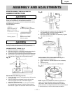
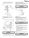
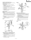
5. Using a rubber mallet, plastic-tipped hammer, or a
block of wood and a hammer, firmly tap the chuck
upward into position on the spindle shaft.
Fig. I
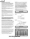
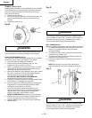
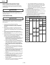
INSTALLING LIGHT BULB (Fig. J) (not included)
1. Install a light bulb (no larger than 60 watt) into the
socket inside the head.
Fig. J
1
2
WARNING
1. To prevent injury resulted from heat of the light bulb
(1). Never touch the light bulb (1)!
2. To prevent electric shock. Never touch the bulb socket
(2) when the plug from the power source is connected.
DRILL PRESS ADJUSTMENTS
CAUTION: All the adjustments for the operation of the drill
press have been completed at the factory. Due to normal
wear and use, some occasional readjustments may be
necessary.
WARNING
To prevent personal injury, always disconnect the plug
from the power source when making any adjustment.
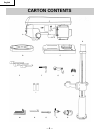
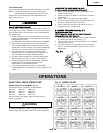
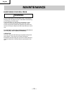
Fig. L
6
5
4
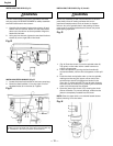
BEVEL SCALE (Fig. L)
NOTE: The bevel scale has been included to measure
approximate bevel angles. If precision is necessary, a
square or other measuring tool should be used to position
the table. To use the bevel scale (6):
1. TIGHTEN the nut (4) on the locking pin in the
clockwise direction to RELEASE the pin from the table
support.
2. Loosen the large hex head bevel locking bolt (5).
WARNING
To prevent injury, be sure to hold the table & table arm
assembly, so it will not swivel or tilt.
3. Tilt the table, aligning the desired angle measurement
to the zero line scribed on the table opposite the bevel
scale (6).
4. Tighten the bevel locking bolt (5).
5. To return the table to its original position, loosen the
bevel locking bolt (5). Realign the bevel scale (6) to the
0° scribed line on the table.
6. Loosen by turning counterclockwise the nut (4) on the
locking pin to the end of the threads. Tap the pin into
its original position.
7. Tighten the bevel locking bolt.
NOTE: The table has been removed from the illustration
for clarity.
WARNING
To prevent personal injury, always disconnect the plug
from the power source when making any adjustment.