


—15
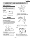
THE LASER GUIDE
Your tool is equipped with our latest innovation, the Laser
Guide , a battery powered device using Class II laser
beams. The laser beams will enable you to preview the
drill bit path on the workpiece to be drilled before you
begin your operation.
WARNING
AVOID DIRECT EYE CONTACT
A Laser light is radiated when the laser guide is turned on.
Avoid direct eye contact. Always turn off the laser and un-
plug the drill press from the power source before making
any adjustments.
A laser pointer is not a toy and should not come into
hands of children. Misuse of this appliance can lead to
irreparable eye injuries.
Any adjustment to increase the laser power is forbidden.
When using the laser pointer, do not point the laser
beam towards people and /or reflecting surfaces. Even
a laser beam of lower intensity may cause eye damage.
Therefore, do not look directly into the laser beam.
If the laser pointer is stored for more than three
months without use, please remove the batteries to
avoid damage from possibly leaking batteries.
The laser pointer includes no servicing components.
Never open the housing for repair or adjustments.
On units equipped with the Laser-Guide attachment,
repairs shall only be carried out by the laser
manufacturer or an authorized agent.
Laser Warning label: Max output <1mW DIODE
LASER:630-670nm, Complies with 21CFR 1040.10 and
1040. 11.
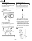
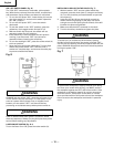
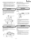
ADJUSTING THE LASER LINES (Fig. Q-1)
A. How to check the Laser-beam Alignment?
1. Adjust the table height so it is 7 inches below the
bottom of the chuck
2. Scribe a round circle (approx. 1/8 inch) on a piece of
scrap
wood.
3. Insert a drill bit into the chuck and tighten.
4. Lower the quill and align the scribed circle with the
drill bit & fasten the wood to the table.
5. Turn on the laser and verify the laser lines (x) are
centered onto the scribed circle.
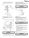
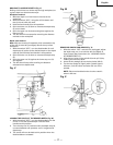
B. ALIGNING THE LASER-BEAM (Fig. Q-1)
To adjust the laser lines:
NOTE: Lower the chuck quill and lock it in place by
spinning the lower depth stop nut.
1. Lower the drill press quill One inch and lock into place
by spinning the depth stop (see Fig. Y).
2. Turn the screw (1) until the laser beam is at it's desired
setting.(both screws)
If the laser guide is not centered on the scribe then
contact your Authorized Service Center for bolt (2)
adjustments.
Fig. Q-1
3
2
1
OPERATIONS
BASIC DRILL PRESS OPERATIONS
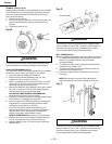
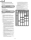
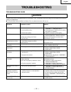
SPEEDS AND BELT PLACEMENT (Fig. R)
This drill press has 12 speeds, as listed below:
250 min
-1
600 min
-1
1620 min
-1
340 min
-1
650 min
-1
1900 min
-1
390 min
-1
990 min
-1
2620 min
-1
510 min
-1
1550 min
-1
3100 min
-1
See the inside of the pulley guard for same chart as
shown in figure R.
250 min
-1
340 min
-1
390 min
-1
510 min
-1
600 min
-1
650 min
-1
990 min
-1
1550 min
-1
1620 min
-1
1900 min
-1
2620 min
-1
3100 min
-1
BEL T:A-1,4-4 BEL T:A-1,3-3 BEL T:B-2,4-4
BEL T:B-2,3-3 BEL T:C-1,4-4 BEL T:A-1,2-2
BEL T:D-4,3-3 BEL T:C-3,2-2 BEL T:B-2,1-1
BEL T:D-4,2-2 BEL T:C-3,1-1 BELT:D-1,1-1
3.
1
2
3
4
5
6
7
8
9
10
11
12
—
WARNING
To avoid possible injury, keep the guard closed, in place,
and in proper working order while the tool is in operation.
Fig. R - SPEED CHART
English
Guide
Guide