


— 14 —
English
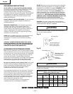
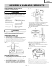
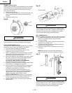
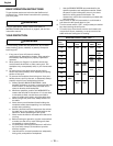
SPINDLE / QUILL (Fig. N)
Rotate the feed handles counterclockwise to lower spindle
to its lowest position. Hand support the spindle securely
and move it back and forth around the axis. If there is
play, do the following:
1. Loosen the lock nut (1).
2. Turn the screw (2) clockwise to eliminate the play, but
without obstructing the upward movement of the
spindle.
3. Tighten the lock nut (1).
Fig. N
1
2
WARNING
To prevent personal injury, always disconnect the plug
from the power source when making any adjustment.
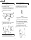
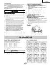
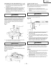
QUILL RETURN SPRING (Fig. O)
The quill return spring may need adjustment if the tension
causes the quill to return too rapidly or too slowly.
1. Lower the table for additional clearance.
2. Remove from the Hub Assembly; cap, nut, two
washers and hub, as shown in Fig. O.
3. Place a screwdriver in the lower front notch (1) of the
spring cap (2). Hold it in place while loosening and
removing only the outer jam nut (3).
4. With the screwdriver still engaged in the notch, loosen
the inner nut (4) just until the notch (5) disengages
from the boss (6) on the drill press head.
CAUTION: DO NOT REMOVE THIS INNER NUT,
because the spring will forcibly unwind.
5. Carefully turn the spring cap (2) counterclockwise with
the screwdriver, engaging the next notch.
6. Lower the quill to the lowest position by rotating the
feed handle in a counterclockwise direction while
holding the spring cap (2) in position.
7. If the quill moves up and down as easily as you
desire, tighten the inner nut (4) with the adjustable
wrench. If too loose, repeat steps 3 through 5 to
tighten. If too tight, reverse steps 4 and 5.
DO NOT OVERTIGHTEN and restrict quill movement.
8. Replace the jam nut (3) and tighten against the inner
nut (4) to prevent the inner nut from reversing.
9. Replace washers, hub, nut and hub cap in the order
shown below.
Fig. O
Hub Assembly
6
5
4
3
1
2
WARNING
To avoid injury from an accidental start, ALWAYS make
sure the switch is in the “OFF” position, the switch key is
removed, and the plug is not connected to the power
source outlet before making belt adjustments.
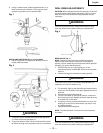
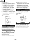
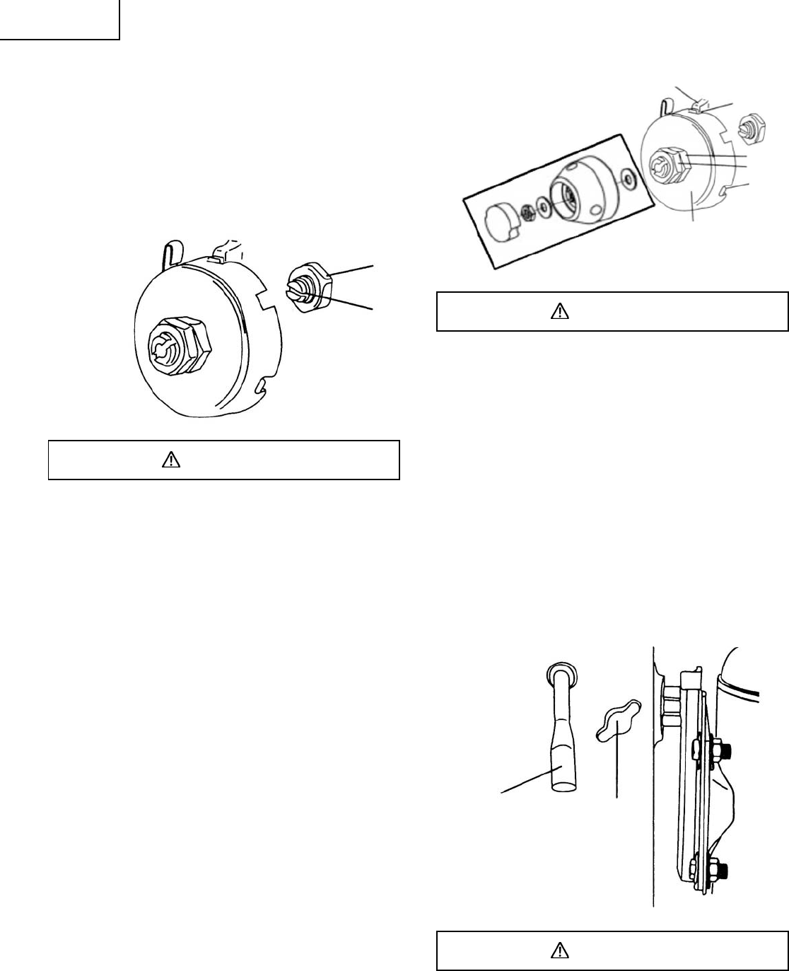
BELT TENSION (Fig. P)
Make sure pulleys are aligned properly as shown in Figure R.
1. To release the belt tension, turn the belt tension lock
knobs (1) on each side of the drill press head
counterclockwise.
2. To tighten the belts, push the belt tension handle (2)
toward the rear (motor) end.
3. To loosen the belts, pull the belt tension handle (2)
toward the front (switch) end.
4. Lock the two belt tension lock knobs (1) by turning
clockwise.
NOTE: Belt tension is correct if the belt deflects
approximately 1/2 inch when pressed at its center.
Fig. P
2
1
WARNING
To avoid injury from an accidental start, ALWAYS make
sure the switch is in the “OFF” position, the switch key is
removed, and the plug is not connected to the power
source outlet before making belt adjustments.