


— — 12
ASSEMBLY AND ADJUSTMENTS
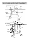
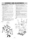
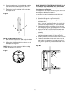
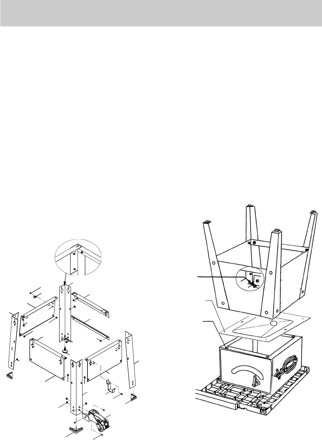
ASSEMBLE TABLE SAW TO STAND (Fig. A, B)
1. Place protective corrugated cardboard or old blanket
on floor to protect the saw table surface.
2. Place the saw up-side down on the protective material
(Fig. B).
3. Position the recessed-side dust chute and the stand
up-side down on the saw base.
NOTE: Make sure front of stand and front of saw are
facing the same direction.
4. Line up four holes in saw base, dust chute and stand.
5. Fasten saw to dust chute and stand using four bolts,
washers and nuts.
NOTE: Place washer on each bolt before inserting into
saw base and through the support. Nut must be flush
against the bracket.
6. Tighten all four nuts.
NOTE: Do not overtighten the locknuts mounting the
base to the stand (you may damage the base).
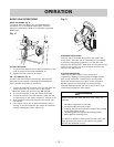
7. Carefully set the saw in its upright position on a clean
level surface.
8. Push down on the lever of right wheel assemblies to
unlock. Push up on the lever of right wheel assemblies
to lock.
NOTE: You will need assistance form another person.
Fig. B
Leg set
mounting
hole
Saw base
hole
Dust chute
mounting
hole
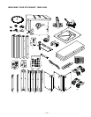
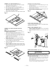
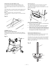
ASSEMBLE STAND (Fig. A)
1. Unpack all parts and group by type and size (Fig. A).
Refer to parts list for quantities.
2. Attach one support (4) to leg (1) using one square
neck bolt (2) and nut (3).
NOTE: Do not tighten bolts until stand is properly
aligned (see step # 7).
3. Attach other end of support to another leg using one
square neck bolt and nut.
4. Join front frame assemblies using support (5) square
neck bolts and nuts.
5. Join rear frame assemblies using short upper support
(6) and short bottom support (7), square neck bolts
and nuts.
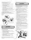
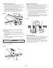
6. Place three rubber feet (8) onto three leg and the
adjustable foot (9) and nut (10) onto the bracket of the
other leg.
7. Attach the hooks (11) and power cord storage (12) to
the frame as desired. The hooks are used to hold the
fence.
8. Place stand on level surface and adjust so all legs are
contacting the floor and are at similar angles to the
floor.Tighten all bolts.
NOTE: Stand should not rock after all bolts are
tightened.
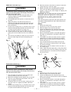
9. Mounting a caster (13) on each leg by tightening three
bolts (14) and nuts (15). Four casters.
NOTE: Two casters marked "A" are used for the Front-
Right & Rear-Left legs, two casters marked "B" are
used for the Front-Left & Rear-Right legs.
Fig. A
1
6
1
1
4
4
12
8
14
15
5
3
3
3
9
10
3
2
7
11
13
1
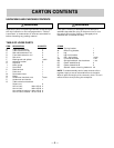
ESTIMATED ASSEMBLY TIME 50~70 MINUTES (2 PEOPLE)