


— — 14
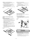
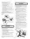
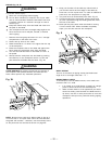
Installing the blade guard assembly (Fig. G)
1. Remove the table insert.
2. Unlock the blade bevel lock knob (1).
3 With the blade evevation handwheel (2), raise the
blade to the maximum height.
4. Using the blade tilting handwheel, tilt the blade to
45 on the bevel scale.
5. Lock the blade tilt locking knob.
6. Locate the splitter assembly mounting bracket (4) in
back of the blade.
7. Cover the blade teeth with a folded cardboard or
position the plastic blade guard over the blade to
protect your hands.
8. Place the two kickback pawls (5) toward the rear of the
table, and align the splitter mounting holes to the
holes in the bracket.
9. Place the steel flat washers (6) on the two bolts (7) and
tread the bolts into the holes.
10. Tighten the bolts with the angled wrench.
Note: Make sure the "anti-kick back pawls" do not get
caught between the insert and the guard, but rest on top
of the insert.
Fig. G
4
5
0
B
L
A
D
E
A
N
G
L
E
A
D
J
U
S
T
M
E
N
T
U
P
U
P
5
1
2
4
6
7
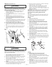
Removing the blade guard assembly (Fig. H)
WARNING
To avoid injury from an accidental start, make sure the
switch is in the OFF position and the plug is disconnected
from the power source outlet.
1. Remove the table insert.
2. With the blade elevation handwheel (1), raise the
blade to the maximum height.
3. Loosen blade lock handle (2) and move the handwheel
(1) to 45 on the bevel scale.
4. Tighten the bevel lock handle.
5. Cover the blade teeth with a piece of folded cardboard
or position the plastic blade guard over the blade to
protect your hands.
6. Loosen the knob (5) and remove the blade guard
assembly, then retighten the knob.
7. Return the blade to 90 and replace the table insert.
Note: Make sure the "anti-kick back pawls" do not get
caught between the insert and the guard, but rest on top
of the insert.
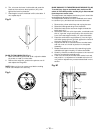
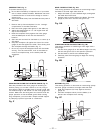
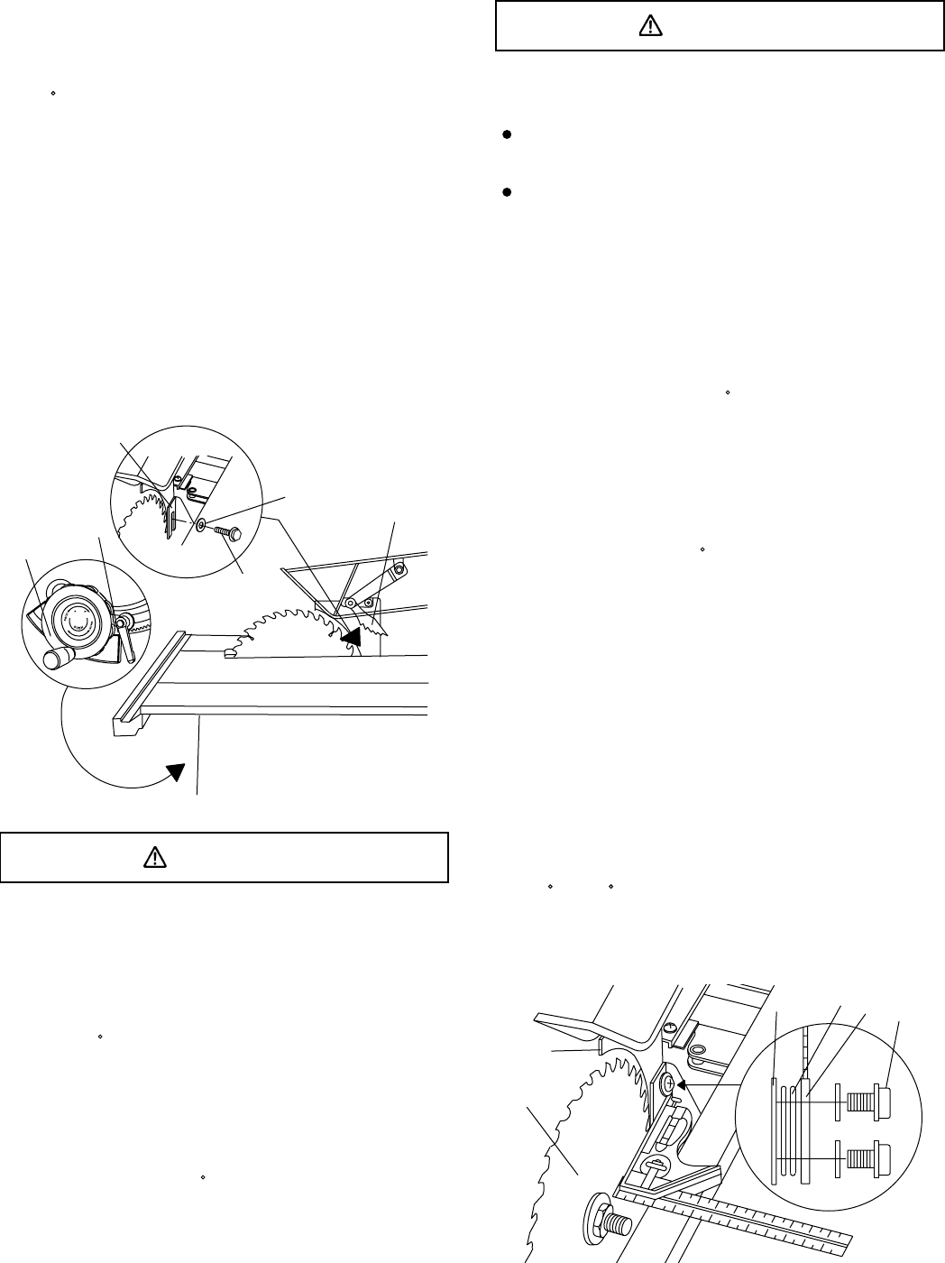
ALIGNING THE BLADE GUARD SPLITTER (Fig. H)
WARNING
To avoid injury from an accidental start, make sure the
switch is in the OFF position and the plug is disconnected
from the power source outlet.
When installing the blade guard, cover the blade teeth
with a piece of folded cardboard to protect yourself
from possible injury.
Never operate this machine without the safety guard
in place for all through sawing operations.
IMPORTANT: The splitter must always be correctly
aligned with the blade so the cut workpiece will pass on
either side without binding or twisting.
1. Remove the table insert and raise the blade to the
maximum height by turning the blade elevation
handwheel clockwise.
2. Lift the blade guard and position it toward the rear of
the table.
3. Adjust the blade to the 90 vertical position by
unlocking the blade tilting lock knob and turning the
bevel tilting handwheel counterclockwise, and then
lock into position.
4. To see if the blade (1) and splitter (2) are correctly
aligned, lay a combination square along the side of
the blade and against the splitter (making sure the
square is between the teeth of the blade).
5. Tilt the blade to the 45 position and check the
alignment again.
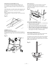
6 If the blade and splitter are not correctly aligned:
a. Remove the blade guard by removing the wing
bolt that locks the guard in place.
b. Loosen and remove the two bolts (3) from the
mounting bracket (7).
7. Place two adhesive washers (5) on the guard
mounting bracket (attached to the saw). Position
them over the corresponding mounting bolt holes
(refer to step 6-b) after removing the adhesive backing
affixed to the washers.
8. Replace the two guard mounting bolts (3) and tighten
securely. Also reattach the blade guard assembly,
affixing it to the machine by its corresponding wing
bolt.
9. Check the splitter and blade alignment again at both
90 and 45 .
10. Add or remove the adhesive washers until the
alignment is correct.
11. Replace the table insert.
Fig. H
1
2
7
5
2
3