


— 15 —
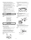
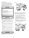
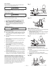
RIP FENCE INDICATOR ADJUSTMENT (Fig. Q)
1. The rip fence indicator (6) points to the measurement
scale (8). The scale shows the distance from the side
of the fence to nearest side of the blade.
2. Measure the actual distance with a rule. If there is a
difference between the measurement and the
indicator, adjust the indicator (6).
3. Loosen the screw (7) and slide the indicator to the
correct measurement on the scale. Tighten the screw
and remeasure with the rule.
WARNING
To avoid injury from an accidental start, make sure the
switch is in the OFF position and the plug is not connected
to the power source outlet.
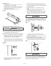
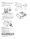
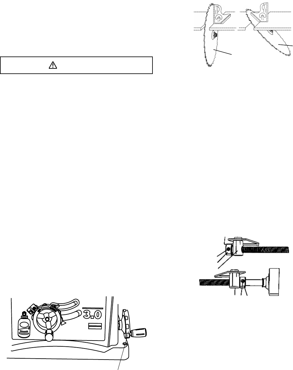
ADJUSTING THE 90° AND 45° POSITIVE STOPS
(Fig. Q-1, Q-2, Q-3)
Your saw has positive stops that will quickly position the
saw blade at 90° to the table. Make adjustments only if
necessary.
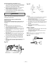
90° Stop
1. Disconnect the saw from the power source.
2. Turn the blade elevation handwheel and raise the
blade to the maximum elevation.
3. Loosen the blade bevel lock handle (2) and move the
blade to the maximum vertical position. Tighten the
lock handle (2).
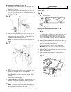
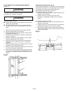
4. Place a combination square on the table and against
the blade (1) to determine if the blade is 90° to the
table. (Fig. Q-2)
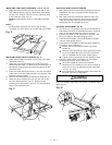
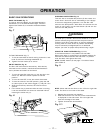
5. If the blade is not 90° to the table, loosen the two set
screws (4), located on the bottom of the table saw,
(Fig. Q-3) with the hex key, and back off the collar.
6. Loosen the bevel lock knob. Turn the blade tilting
handwheel to move the blade until it is 90° to the
table.
7. Adjust the collar (5) so it contacts the bracket (3) when
the blade is 90° to the table. Tighten the two set
screws (4).
Fig. Q-1
2
Fig. Q-2
90° 45°
1
3
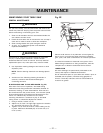
45° Stop
1. With the blade in the upright 90° position, loosen the
bevel lock knob and move the blade to the 45°
position as far as it will go.
2. Place the combination square on the table as shown in
(Fig. Q-2) to check if the blade is 45° to the table.
3. If the blade is not 45° to the table, adjust the screw (4)
(Fig. Q-3) with a screw driver until the blade is 45° to
the table.
4. Tighten the bevel lock handle.
5. Tighten the screw (4) until resistance is felt. Do not
overtighten.
BLADE TILT POINTER
1. When the blade is positioned at 90°, adjust the blade
tilt pointer to read 0° on the scale.
2. Loosen the holding screw, position pointer over 0°
and tighten the screw.
NOTE: Make a trial cut on scrap wood before making
critical cuts. Measure for exactness.
Fig. Q-3
4
5
3
345