


–
11
–
English
1
1
1
1
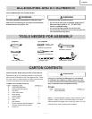
ESTIMATED ASSEMSLY TIME 25~40 MINUTES
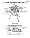
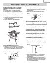
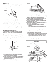
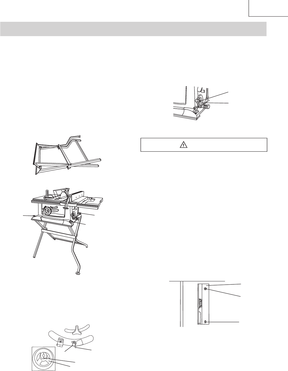
ASSEMBLE THE TABLE SAW TO THE STAND
(FIG. A)
1
. Unfold the leg sets and push down in place.
2. Place the stand on a level surface and adjust the
front-right adjustable foot, so all legs are contacting
the fl oor and are at similar angles on the fl oor.
3
. Match the holes of the stand to the holes on the
bottom fl ange of the saw base.
4. Fasten the saw to the stand using the four handles
(1) then tighten securely .
5. Position the saw on a clean, level surface.
Fig. A
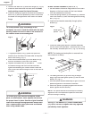
BLADE
RAISING HANDWHEEL (FIG. B)
1. Attach the up ~ down handwheel (1) to the elevation
rod (2) at the front of the saw. Make sure the slots (3)
in the hub of the handwheel (1) engage with the
pins (4).
2. Attach and tighten the dome nut (5-Fig.C)
Fig.
B
1
3
4
2
ASSEMBLY AND ADJUSTMENTS
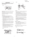
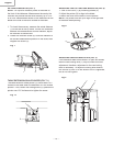
BLADE TILTING HANDWHEEL (FIG. C)
1. Attach the bevel 0° ~ 45° handwheel (6) to the blade
tilting rod on the right side of the saw in the same
manner as above.
2. Attach and tighten the handwheel dome nut (5).
Fig. C
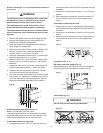
INSTALLING AND REMOVING THE BLADE (FIG. D)
To avoid injury from an accidental start, make sure
the switch is in the OFF position and the plug is
disconnected from the power source outlet.
To avoid serious injury, the rear of the table insert
must be level with the table. If the rear of the insert
is not level with the table, adjust the screw (3) in or
out until the rear of the insert is level to or slightly
above the table. To raise the insert, turn the screw
counterclockwise, to lower the insert, turn the screw
clockwise. NOTE: A rubber adjusting spacer is
provided under rear of insert for this purpose.
1.
Remove the table insert (1) by removing the two
screws
(2, 3). Be careful not to lose the rubber washer that is
on the back screw (3) beneath the table insert.
(Fig. D)
Fig.
D
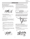
2. Raise the blade arbor (4-Fig. E) to the maximum
height by turning the blade raising handwheel
counterclockwise.
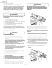
3. Place the open-end wrench (8) jaws on the fl ats of
the saw arbor to keep the arbor from turning
(Fig. F)
and place the box-end wrench (9) on the arbor nut
(5), and turn counterclockwise.
5
6
1
3
2
WARNING