


–
20
–
English
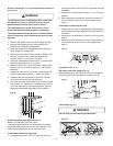
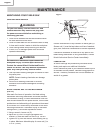
USING WOOD FACING ON THE RIP FENCE
(FIG. HH)
When performing some special cutting operations, add
a wood facing (1) to either side of the rip fence (2).
1. Use a smooth & straight 3/4 in thick wood board
(1) that is as long as the rip fence.
2. Attach the wood facing to the fence with wood
screws (3) through the holes in the fence. A wood
fence should be used when ripping material such as
thin paneling to prevent the material from catching
between the bottom of the fence and the table.
Fig.
HH
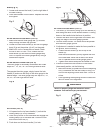
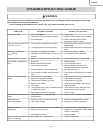
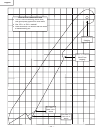
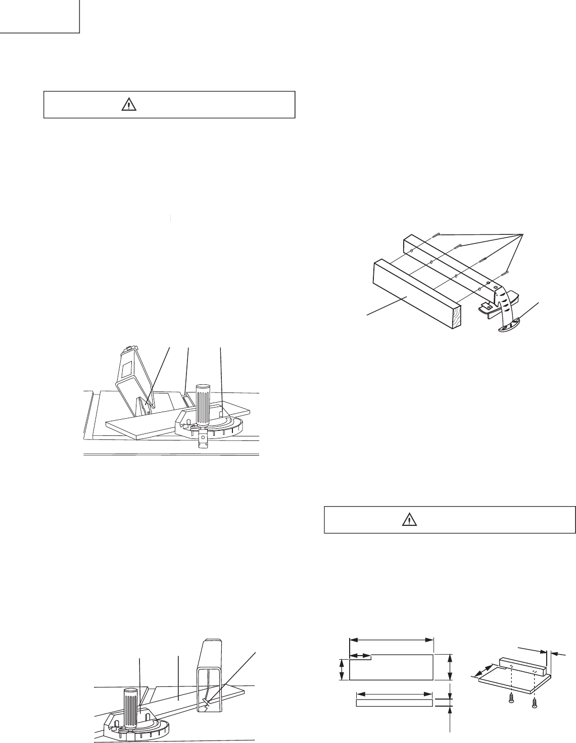
AUXILIARY FENCE (FIG. II)
Making the base:
•
Start with a piece of 3/8 in plywood at least 5-1/2 in
wide or wider and 30 in long or longer.
•
Cut the piece to shape and size shown:
Making the side:
•
Start with a piece of 3/4 in plywood at least 2-3/8 in
wide or wider and 27 in long or longer
•
Cut the piece to shape and size shown:
Putting it together:
•
Put the pieces together, as shown:
Make sure the screw heads do not stick out from the
bottom of the base, they must be fl ush or recessed.
The bottom must be fl at and smooth enough to rest
on the saw table without rocking.
Fig.
II
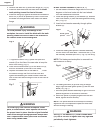
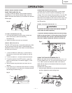
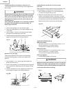
COMPOUND MITER CROSSCUTTING (FIG. FF)
This sawing operation is combining a miter angle with a
bevel angle.
Always work to the right side of the blade during this
type of cut. The miter gauge (3) must be in the right
side groove because the bevel angle may cause the
blade guard to interfere with the cut if used on the
left side groove.
W
hen til
ting the work
piece to 45
° and push it toward
the blade, the blade guard may hit the blade. To
avoid
inju
ry, stop the
work
at that time.
work at that time. work
1. Set the miter gauge (3) to the desired angle.
2. Place the miter gauge (3) in the right side groove (2)
of the table.
3. Set the blade (1) bevel to the desired bevel angle
and tighten the blade bevel lock knob.
4. Hold workpiece fi rmly against the face of the miter
gauge (3) throughout the cutting operation.
Fig.
FF
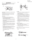
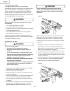
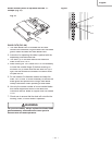
MITER
CUTS (
FIG.
GG)
This sawing operation is the same as crosscutting
except the miter gauge is locked at an angle other
than 90°.
1. Set the blade (1) to 0° bevel angle and tighten the
blade bevel lock knob.
2. Set the miter gauge (3) at the desired miter angle and
lock in position by tightening the miter gauge locking
handle.
3. Hold the workpiece (2) fi rmly against the face of the
miter gauge throughout the cutting operation.
Fig.
GG
WARNING
WARNING
3
2
1
30”
2-5/8”
3-1/2”
3/8” Thick plywood base
27”
3/4” Thick plywood
3/4” Thick plywood
side
5-1/2”
2-3/8”
4-3/4”
1-1/4”
1
1
2
3
1
2
3